Hello,
Im new to Arduino and have a specific project in mind to work on. I would like to build a wireless remote for an analogue camera.
Someone has done this before and recorded their process, although not that clearly for a beginner. Here is the blog with some useful photos and info: http://handya.co.nz/post/43777800968/wireless-remote-for-fuji-x100-camera-or-leica [/url]
Here is the layout:
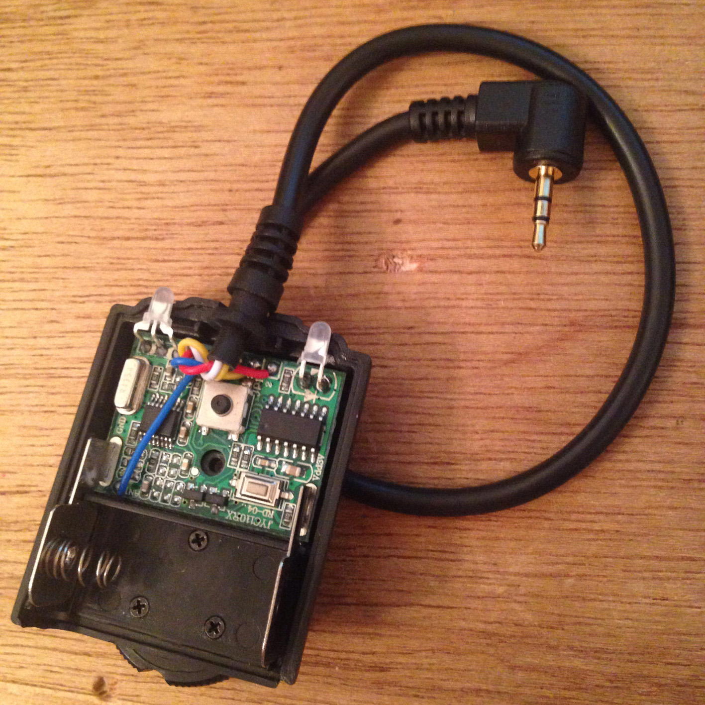
I have purchased a Wireless Remote control (http://www.ebay.com/itm/Wireless-Shutter-Release-Remote-Control-for-Canon-650D-60D-550D-600D-1100D-1000D-/271320473626?pt=Camera_Camcorder_Remotes&hash=item3f2bf5e01a)
What I intend to do is wire an Arduino board to a servo and the receiver, so when a signal is sent from the transmitter the receiver sends signal to the Arduino and runs the servo that will trigger the analogue cable release. This is the the same as the blogger, i just dont quite understand the construction of his circuit.
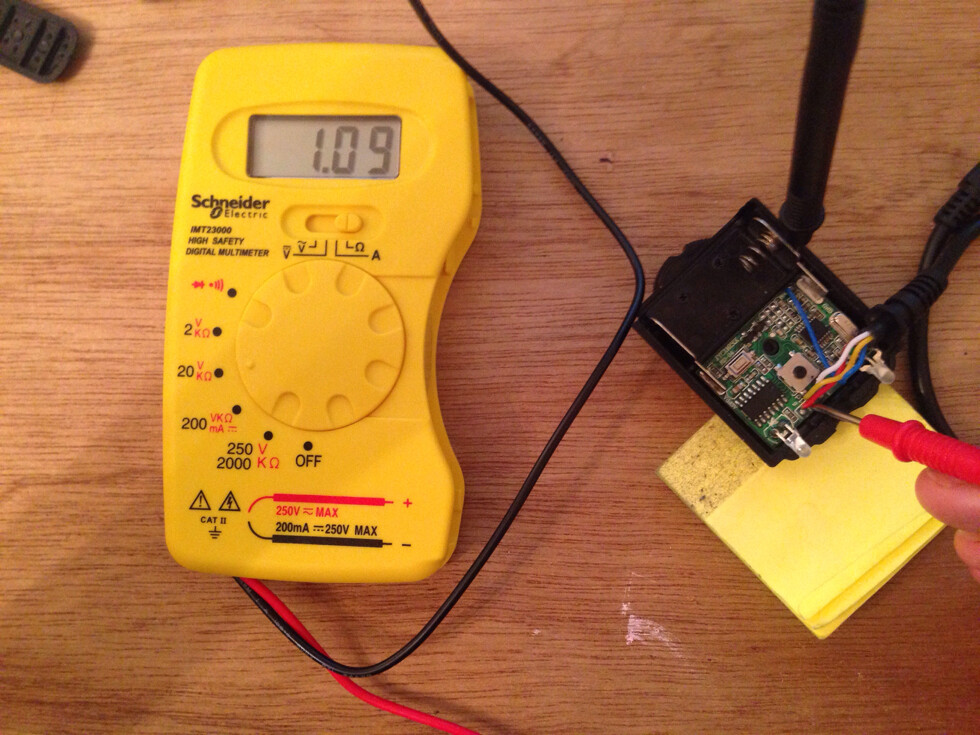
Ideally it would be really useful to get some help with the building of the circuit. For example the receiver is 3V whereas I know that Arduino boards run on 5v. You can get 3V or 5v Adafruit trinkets, I have a 5v one and can always buy a 3v one if needed. I’m a little confused on regulating the circuit. I’m also a bit unclear of hacking the wireless remote, what connects to what? Reading through the original instructions helps, but I’m not yet fluent with Arduino and building circuits, especsaily from looking at realistic ciruicts and copying them, im more use to looking at the circuits detailed in the Arduino book.
I have also read a lot about 9V batteries not running efficiently with Arduino. Many people seem to use AA batteries instead. Would this be an effective update to make the project more power efficient? Or is it suitable with a 9v supply?
I know there are a lot of questions here, but any advice would be greatly appreciated.
Below is the insturctions copied from the blog, but without the photos, and code supplied by the original builder:
Wireless Remote for Fuji X100 Camera (or Leica)
I need the ability to wirelessly take photos, however my camera did not have a conventional shutter release, it has the old fashioned ”cable” release.
After playing around and buying some cheap cable releases off Ebay I was able to build a working wireless shutter using an Arduino, Servo, and a cheap wireless shutter for a Canon DSLR.
I had thought of using an IR remote however I am planing on using this outside and im not sure how well IR works in direct sunlight. So I went for an RF option.
These remotes have the half press focus option, but as I would not be needing this, and when you bend the wire cable it changes the length of the “press” meaning that it would not always work. To make it more reliable it only takes photos without focusing but as I am going to be using manual focus its not a problem.
I mounted a servo in a small enclosure and pushes on the cable firing the camera shutter.
The servo is controlled by and Arduino that triggers the servo when it gets the command from the wireless remote.
I also mounted the hot shoe adaptor from the old shutter
Parts List:
Arduino (ATmega 328p microcontroller)
- I would recommend Adafruit Trinket instead
Servo - A small one will work fine
Wireless Shutter Release Remote Control - See Photo Above for more information
- Cheap ones available on ebay
- I was able to take the “hot shoe” off the receiver and mount it to my case so it could be attached to the camera.
Mechanical Shutter Release Cable - See Photo Above for more infomation
- Cheap ones available on ebay
5volt Regulator and Capacitor - This might not be need if Adafruit Trinket used instead.
Power Switch
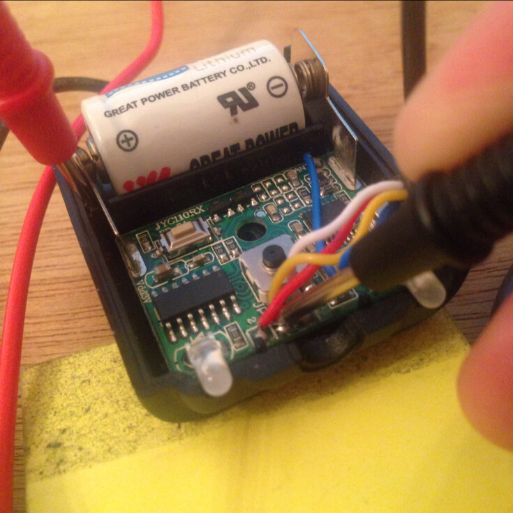
9Volt Battery
Case
More Information:
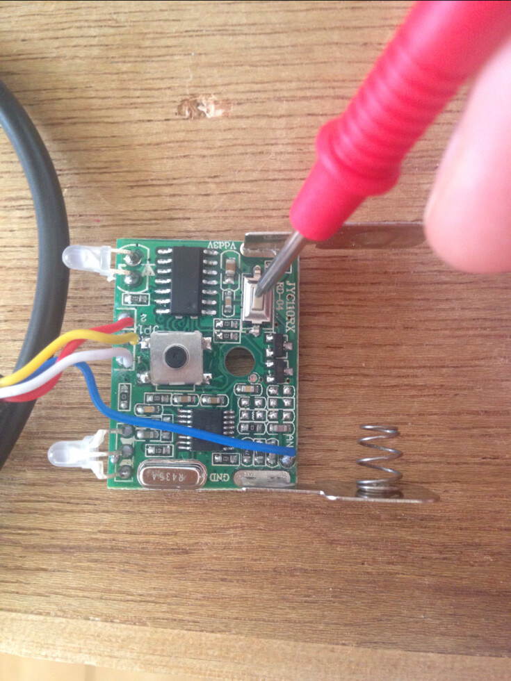
Pin 13 of the Arduino was wired via a transistor to the power button of the wireless shutter receiver, this way when the power was turned on the Arduino would power on the receiver automatically.
The wireless shutter has a “double press” button, a half press would focus a normal camera and a full press would take a photo. There are three wires coming from the receiver, “Ground” “Focus” “Shoot”.
Ground is connected to the Arduino ground, “Focus” connected to pin 12, and Shoot Connected to pin 11 and the servo is connected to pin 10.
I never used the focus input as the servo was not accurate enough.
When the “Shoot” pin goes LOW the servo is driven to shoot position for 500ms (See code for more info)
The two LEDs seen in photos are part of the receiver module.
Here is the code:
/*
*************************** Wireless Shutter For X100 Camera **********************************************
( cable release cameras )
code for controlling a servo thats wirelessly triggered
Created 23 February 2013
by Andrew D. Farquharson
More at www.handya.co.nz
*/
#include <Servo.h>
Servo servo;
int FocusButton = 12;
int ShootButton = 11;
int FocusState = 1;
int ShootState = 1;
int powerbutton = 13;
void setup() {
pinMode(FocusButton, INPUT);
pinMode(ShootButton, INPUT);
pinMode(powerbutton, OUTPUT);
servo.attach(10); // start servo
servo.write(35);
delay(1000);
digitalWrite(powerbutton, HIGH); // power on wireless module
delay(3000);
digitalWrite(powerbutton, LOW);
}
void loop() {
FocusState = digitalRead(FocusButton); //get wireless module state
ShootState = digitalRead(ShootButton);
if(FocusState == 0){ // drive servo to take photo
servo.write(120);
delay(500);
servo.write(35);
}
delay(10);
}