Your schematic is not only confusing, it is wrong. The output of the regulator is shorted to ground, and it appears that the ground pin of the servo is connected to nothing but the bypass capacitor.
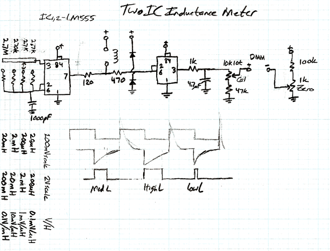
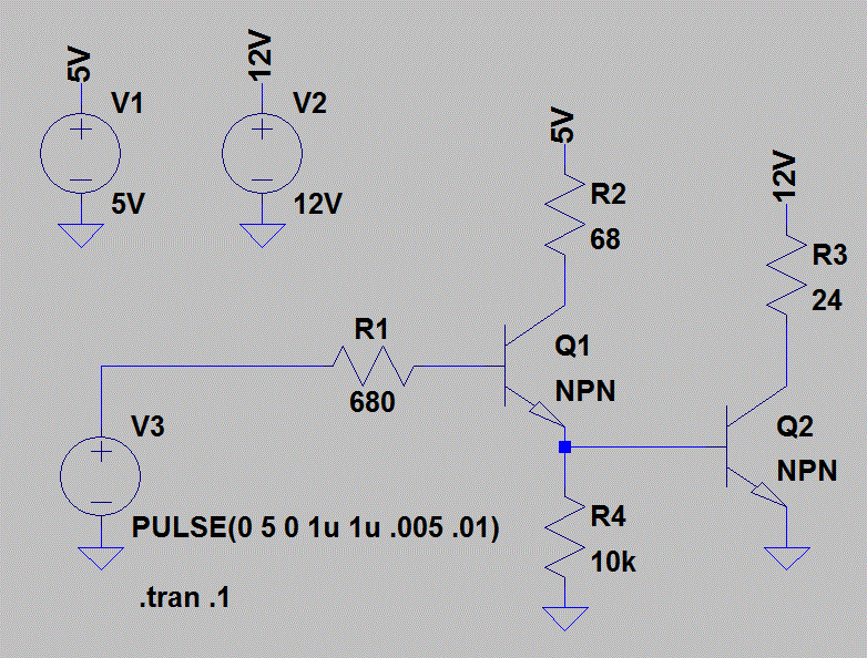
Use the ground symbol so you don't have a mishmash of wires running everywhere. You can do the same with a small circle labeled "5V" to indicate the 5V supply line. Signal flow should go from left to right as much as possible. Power should go + supply on top, ground on the bottom, or - on the bottom if there is a negative supply. These are often called "global connections".
I really hate what Fritzing and Make magazine are doing to schematics.
http://opencircuitdesign.com/xcircuit/goodschem/goodschem.html
Remember that the point behind using schematics rather than a pictorial is to make it more clear what the circuit is doing and how it is wired up.


