OP is probably waiting for his email to tell him someone has posted in his thread.
I tell you that facility is "super reliable" :o :o :o :o :o :o :o :o :o :o :o :o :o
Tom... ![]()
OP is probably waiting for his email to tell him someone has posted in his thread.
I tell you that facility is "super reliable" :o :o :o :o :o :o :o :o :o :o :o :o :o
Tom... ![]()
Apologies everyone,
You were right Tom, I was waiting for an email notification that someone had replied!
I wanted a switch with three positions - off and two other modes. Found this on ebay:
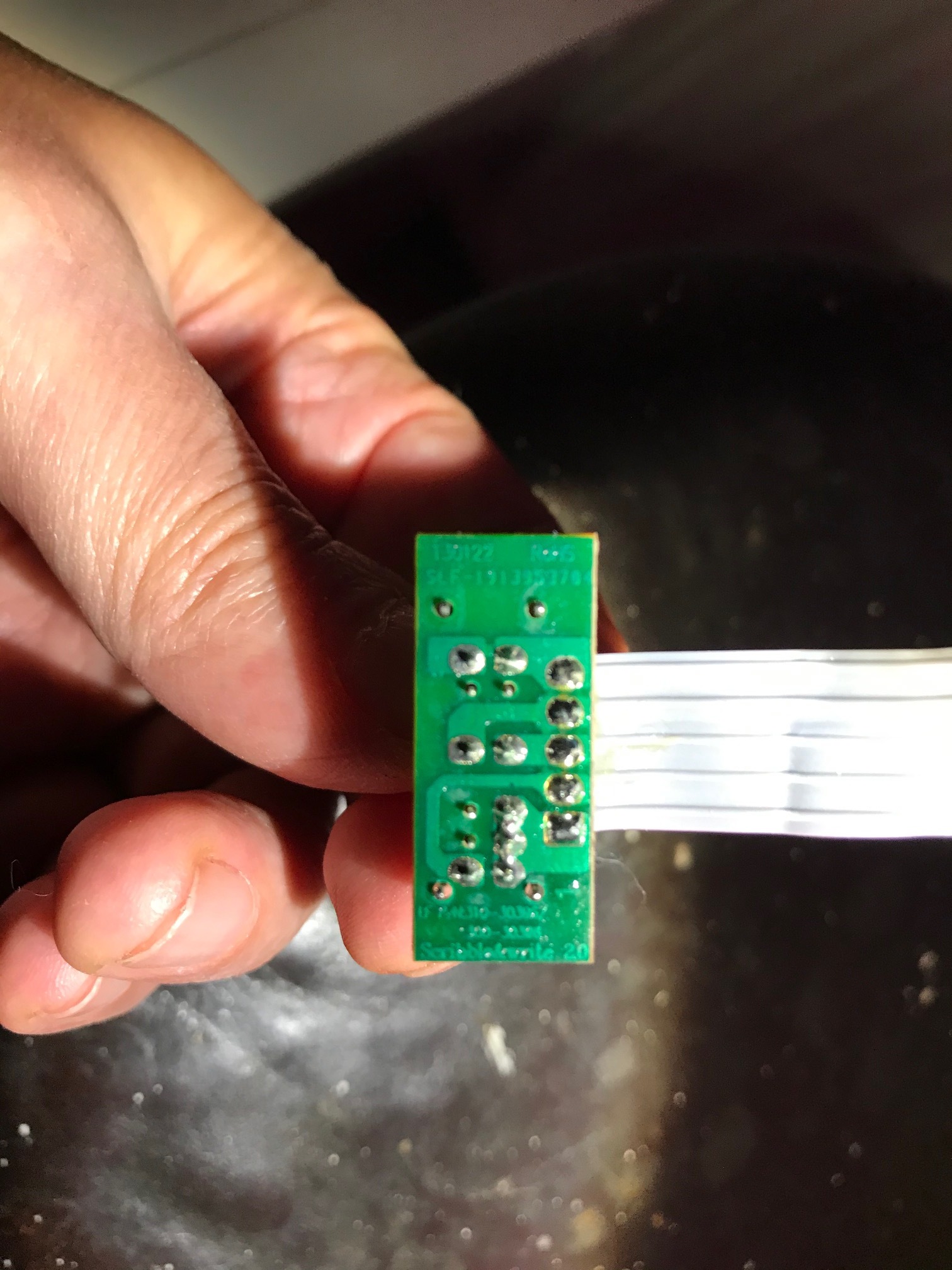
Picture of back is attached.
Just need to know which wire goes to 5V which to ground and which are data pins.
As you've all probably guessed I'm new to this forum so yet more apologies if I haven't followed the correct protocol!
Hi,
Do you have a DMM, Digital Multimeter?
Does your switch have 3 positions when you move the lever?
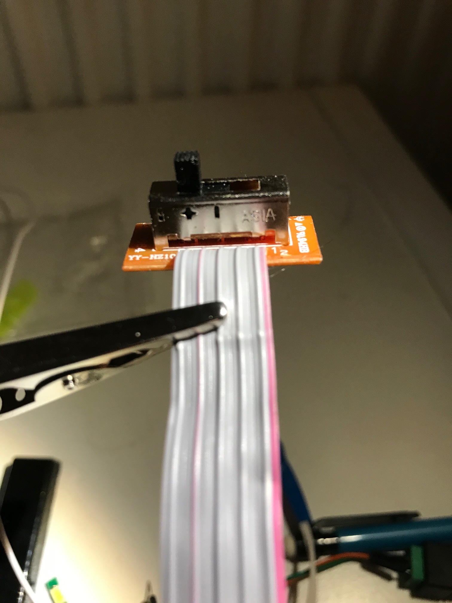
I see 12pins and coming out of the base of that switch?
Is there a number on the side of the switch?
Thanks.. Tom... ![]()
"Just need to know which wire goes to 5V which to ground and which are data pins."
What??
You see which pins are connected to which but only way to be sure is a continuity Truth Table showing
continuity from which pins to which for the three
positions.
Here's a side view.
Yes the switch has three positions.
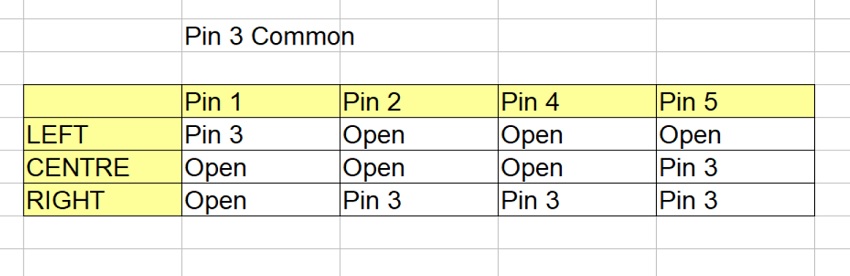
In left position there's continuity between 1 and 3.
In centre position there's continuity between 3 and 5.
In right position there's continuity between both 3 and 5 and 2 and 4.
What I'm trying to do is extremely basic:
In right position send message to one LED pin.
In centre position send message to a different LED pin.
In left position send to neither.
Hope this clarifies things a bit.
Thus, connect Pin 3 to ground, and Pin1 and Pin2 to digital inputs with pull ups enabled.
So it is of course, not a "one pole" switch.
Both Tom and aarg have got it wrong. ![]() As per #25, pins 2 and 4 are one pole, pins 1, 3 and 5 are the other as the PCB illustrates.
As per #25, pins 2 and 4 are one pole, pins 1, 3 and 5 are the other as the PCB illustrates.
If you ground 2 and 3, then pin 4 will tell you the "right" position and pin 1 will tell you the "left" position. You cannot with this PCB, have "neither" at one end, it must be in the middle.
There are however, pins on the switch unused on this particular PCB. ![]()
Hi,
The truth table was generated purely on the OPs posted info.
It will provide the function he needs.
Unless
In right position there's continuity between both 3 and 5 and 2 and 4.
Means 3 and 5 connected, and separately 2 and 4 connected.
Not all 4 connected together.
Tom... ![]()
A power/audio switch from Scribble & Write Learning Pad from LeapFrog.

It strikes me that this thread would be best located in Device Hacking Device Hacking - Arduino Forum
To clarify Tom.
I meant 3 and 5 connected, and separately 2 and 4 connected.
Not all 4 connected together.
Sorry for any confusion.
This switch seems to have opened a can of worms. All I wanted was a simple slide switch which had three positions - left=off and two different on modes.
If there's and more user friendly switch available which does this job I'd be happy to know!
johnty57:
All I wanted was a simple slide switch which had three positions - left=off and two different on modes.
Could be hard to find - most switches of this kind are centre-off. However, you could read the switch positions of such a switch (connected to 2 data inputs)) and do what you want with the outcome, e.g.
left on - interpret as OFF selected,
both off - interpret as MODE1 selected,
right on - interpret as MODE2 selected.
johnty57:
This switch seems to have opened a can of worms. All I wanted was a simple slide switch which had three positions - left=off and two different on modes.
If you are merely going to connect the switch to Arduino inputs, it does not matter which is off, you deal with that in the code.
johnty57:
If there's and more user friendly switch available which does this job I'd be happy to know!
The switch itself will actually do whatever you want, it is the particular PCB that limits you. ![]()
Thanks for your help everyone. Much appreciated.