What is the most handy way to connect an Arduino Nano to resistors, capacitor, and an audio input so that the whole construction fits accurately into a small enclosure?
Wiring diagram:

Hi @kvantum. I like to use stripboard:
You can get it from most of the usual sources of electronics components.
Alternatively, you can get something similar called "protoboard" or "perfboard":
The difference between stripboard and protoboard is that stripboard has electrical connections between each row of holes, which means that connections are made for you by the board (similar to a solderless breadboard) and you only need to make cuts (which is done by hand with a couple of twists of a drill bit) at the specific points where you don't want electrical continuity. With protoboard, you there are no electrical connections between each hole so you must make a connection (usually done with a blob of solder) wherever you want one between holes. You can get more compact circuits with protoboard, but making the solder jumpers is a bit tricky and time consuming.
Hm. Interesting wiring of that pot - between 3.3V, Vref(wiper) and A0? What will be the result of that?
Thanks. I wouldn't like to use protoboard or perfboard since it's already finished design, not a prototype.
OK, then you will want to use KiCad to design a PCB and then send the design to one of the PCB manufacturers (e.g., JLPCB).
A0 performs the "GND" function.
Yes, I was thinking about a PCB: it has to be a separate board for these additional components.
#define POT_GND A0
#define POTENT 1            // 1 - use potentiometer, 0 - use internal 1.1V reference voltage source
void setup() {

  pinMode(POT_GND, OUTPUT);
  digitalWrite(POT_GND, LOW);

  // to increase accuracy, we reduce the reference voltage,
  // by setting EXTERNAL and connecting Aref to the 3.3V output on the board via a divider
  // GND --- [10-20 kOhm] --- REF --- [10 kOhm] --- 3V3
  // in this circuit, GND is taken from A0 for ease of connection
  if (POTENT) analogReference(EXTERNAL);
  else analogReference(INTERNAL);
Please connect the gnd end of the pot to GND, not a controller output.
You can do these things with strip/protoboard and wires.
Have you built the prototype yet?
Strip board can make a nice final product if used properly and only a small number of unit is required.
I would suggest you plug the Nano into a strip of header socket on your board, rather than solder it directly to the PCB.
This was a rough prototype during a POC session.

Tom... ![]()
![]()
![]()
![]()
No, I haven't built a prototype yet.
Breadboard or using a circuit board. There are other ways. Using nylon standoff insulators you could mount your Arduino in a box and just use a small circuit board for your components.
I began this before TonGeorge posted his excellent post with pictures. ![]() Then my phone rang followed by my dinner showing up.
Then my phone rang followed by my dinner showing up. ![]()
Ron
Well build it on protoboard, easy to change components as you go.

Tom... ![]()
![]()
![]()
![]()
How are the standoff itself attached to the enclosure? Just bolted on from the back of the casing? In that case, the back of the casing will be uneven.
JLCPCB
I generally just use standoffs which are drilled and tapped on each end. I place my board on my box and mark where I want to drill the holes. Years ago I bought a kit like this. They come in US and Metric
Ron
Bad practice to power/ground sensors with a pin.
Which sensor.
Can't just lower Aref if this is a ratiometric (pressure) sensor, because that will make the sensor also sensitive to Nano supply voltage variations.
Leo..
Then please draw your solution, show how it should be. (preserving existing functionality)
As mentioned earlier, connect it to GND.

Depending on how many wires your talking about, it might be as simple as just installing your components to your enclosure and just wiring everything to your Nano as well as using a common ground and power.
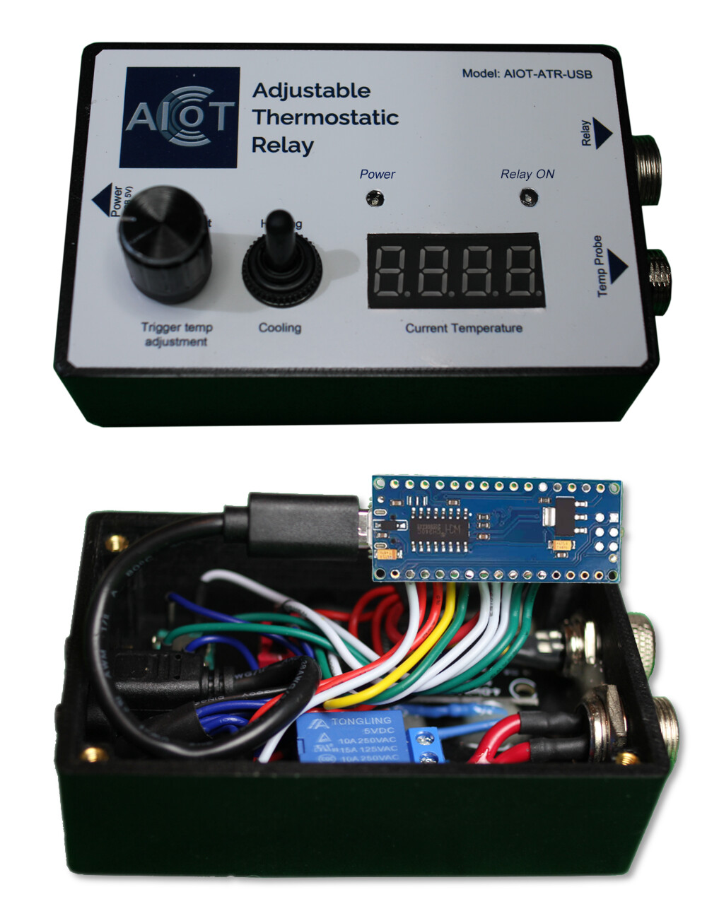
I did a Nano project creating a Thermostatic Relay from this Online UDEMY course using a Nano and this is the route I chose. This makes sense if you dont have too many components and if noise for your sensors is not too big an issue. Here are a couple of pictures of how my project ended up using this method (I used a 3D printer to make the enclosure with all the holes for the components):