If I have two 2.5 volt capacitors and if I wire them in series, and if I supply to them 3.3 volts, then its output should equal 5 volts. No, the correct answer is 3.3 volts. Why is that? It seems logical. If I supply each one with 3.3 volts, then they should all receive their required voltage and when I tap into the circuit, it seems that I should be getting their combined voltage, which I am not. Am I doing something wrong? Or am I looking at capacitors incorrectly?
Also there's no such thing as a 2.5 volt capacitor, capacitance is measured in Farad not in voltage. For instance on electrolytic capacitors you'll see a voltage/temperature rating like 25V/80C. These are the maximum voltage/temperature ratings for that capacitor
I have several 470 microfarad 6.3v capacitors also. I am assuming that the max voltage is 6.3v, thus I cannot supply nor can it hold more than 6.3 volts. Is that correct?
If I supply 6 volts to three capacitors (i.e. described above), I find that each one contains ~2 volts and begins to slowly dissipate to 0 volts as I am measuring volts, yet the other capacitors remain at their 2 volt charge. And, if I add another capacitor, I find that its total output is still 6 volts and that each capacitor still holds a charge of roughly 2 volts. Therefore, I am only cloning 2 volt armies.
Description: Yes you read that correctly – 1 Farad capacitor. This small cap can be charged up and then slowly dissapated running an entire system for hours. Combine two in series for 0.5F/5V. Do not over voltage or reverse polarize these capacitors.
And yes there 2.5 volt used like a fast charged battery in toys and stuff
DO not OVER Charge these they can and will hurt you. 2volts is a safe charge for them.
My main goal was to trigger a 3vdc relay using an IR receiver that was emitting .1 volts. I am not sure if this is the proper setup but it works. The IR receiver is the standard 3 pin module, so I put vcc and gnd to 6v, and the emitter to the negative side of the coil. I wired the positive side of the coil to the positive side of the capacitor and the negative side of the capacitor to 6v gnd. I press any button on my remote and the relay activates. Pretty cool.
You really do not understand what is happening here.
You will for sure do damage.
Lets just hope you will be able to keep personal injury because of that, to a minimum.
MAS3:
You really do not understand what is happening here.
You will for sure do damage.
Lets just hope you will be able to keep personal injury because of that, to a minimum.
Thank you, I too hope to keep from hurting/murdering myself.
Do you care to help me understand what it is I am doing? It appears that my goal has been achieved, but you say that I am in danger. How so?
Very strange, the forum said I was banned until I cleared my history...
Anyway, thanks for the clarification. I have seen partially what you have described -mushroomed capacitor. I doubt that my 6 volts is going to cause an explosion in this case, but I will certainly be on the look out for failing caps.
EvaTech:
I doubt that my 6 volts is going to cause an explosion in this case, but I will certainly be on the look out for failing caps.
Nope. Those 2.5V supercapacitors are extremely sensitive to overvoltage.
You should also never connect them in series because it's very easy for them to charge at different rates in which case one of them will receive more volts than the other and be damaged.
The way i see it (although no degrees in engineering are present):
If there are 3 "empty" caps in series, they all have an effective ohmic value of zero Ohm on DC(I know it not normally in ohm's but bare with me here). When you charge them there resistance will go up.
When you connect the lot a somewhat large current will go through the caps to charge them, just for a brief millisecond and the voltage it spread equally because of the equal lack of resistance.
But when one of the caps is charged a little more than the others due to the electron, flow the voltage on this cap will rise because the ohmic resistance increases. Then a few milli- or microseconds later the other caps will be charged the same as the first one and it's one big, equal voltage sharing family again. So theoretically the entire supply voltage will be over 1 of the caps for a very small amount of time (Somewhere in the milli- of microseconds).
Eventually this will cause it to break.
This, and the fact that not all caps are EXACTLY the same give or take 1 to 20%, is why i'm suggesting to buy a nice 6.3V cap at your local electronics store.
The normal method of getting seriese capacitors to shair the voltage across them equally is to but an identical resistor in parallel with them all. Normally these are high values so they don't contribuites too much to the leakage.
As the the OP i have never come across such a twisted way of thinking, your components will not last long. The output of an IR reciever is an open collector transistor and if you are measuring it as 0.1V this is just because of the base collector leakage in the transistor.
I think that I said 2.5v just to make the math as easy as possible, not for you, but for myself... lol
Here is what I have going on and works great! I have one 470 microfarad capacitor rated at 16v, I have another 680 microfarad capacitor rated at 10v. Between the two, they hold a charge of ~6 volts. I supply 6 volts. I tap into the series to power a 12v buzzer, with a voltage range of about 3v to 12v. Therefore, I have effectively created an IR Frequency Detector. It works like a Geiger Counter -the closer you get to something emitting IR frequencies, the louder the beeps get. So far, I used it to help identify a good place to fly my s107g indoor copter. Turns out, the living room is a terrible place to fly.
Note, the circuit never fails, even after heavy use.
Grumpy_Mike:
You ned to draw a schematic. There are serious inconsistencies in your description.
You can not have a charge of -6V on an electrolytic cap.
Just because your components have not failed yet does not make it a good or even valid circuit.
I agree. You supply a voltage of 6V, therefore your Caps will hold a voltage of (ideally) 6V. Not 10V or 16V.
But if you do please tell me! it would solve the worlds power problems with just capacitors...
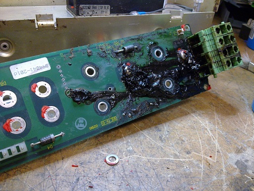
I used to work with Siemens programmable controllers for building automation (Siemens PRV units from the 1980's for those wondering).
Whenever there was a blackout or a lightning strike in the area the following week the caps inside some units would either leak or blow up. If we where lucky we caught it fast before it corroded the entire PCB and there was nothing left but molten plastic containers...
But i'm getting off topic here!
EvaTech, could you draw a schematic of your setup? It's so much better for us if we know what your talking about.
Forgive me if this doesn't make any sense whatsoever. This is my FIRST schematic! I looked over my circuit multiple times and to me the following drawing represents what I have done.
And, because I have probably done that wrong, here is a picture of my circuit:
If you need a video of it actually working, I could probably arrange that too.