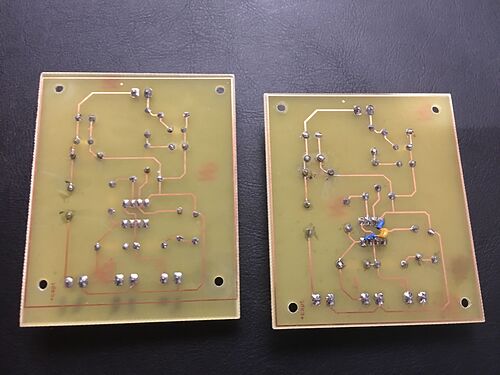
The problem with the actual circuit is that as soon as I power it with 12 V the second diode (BZT) breaks.
The BZT03C36 has a zener voltage of 34 to 38 Volts. So if it breaks then the zener is broken or you do not have a BZT03C36 in the first place. To my eye that diode looks like a small signal diode and not the shape the data sheet suggests it is.
Hi,
Hum, I think I know my mistake!
I chose a wrong zener 3.3V instead of the 36V 
So it obviously not surprising that the diode breaks. I feel stupid to don't have a check before.
I bought ten 0.1 uF ceramic capacitors so I can change also C1. Do you think it could be a good idea?
Thank you again,
Pm
powergravity:
I use I/O 1 on the LMI 393.
With Vbat = 12.05 V and Vlm393 = 4.89 V I get:
V1 = 11.36
V2 = 1.68 V
V3 = 1.18 V
Thank you in advance,
Pm
V1 here tells me if its 3.3V zener then its cooked and open circuit.
Tom....

I am checking the electronics component stock at the laboratory and I only have zener 33V instead of 36V, it should work?
What do you suggest about C1 ceramic or mylar capacitor?
Thank you,
Pm
I would like to acquire wheel speed signal on another motorcycle 
It would be too simple to have the same sensor technology, it is a VRS (variable reluctance sensors). The positive point is that I found more topics for this kind of WSS.
I read that it exists some chips able to directly interface VRS with microcontroller MAX99XX.
Is there someone who have ever used those chips?
Thank you,
Pm
I hope do some tests tomorrow.
Finally, I did 2 circuits (front and rear wheels), one with the recommended modifications and the other like it was when I wrote the first post. We will be able to see the difference with the results.
Thank you,
Pm


