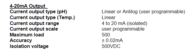
I have a pH controller that can output two 4-20mA signals. One for pH, and one for temperature. The outputs on the controller have a + and -
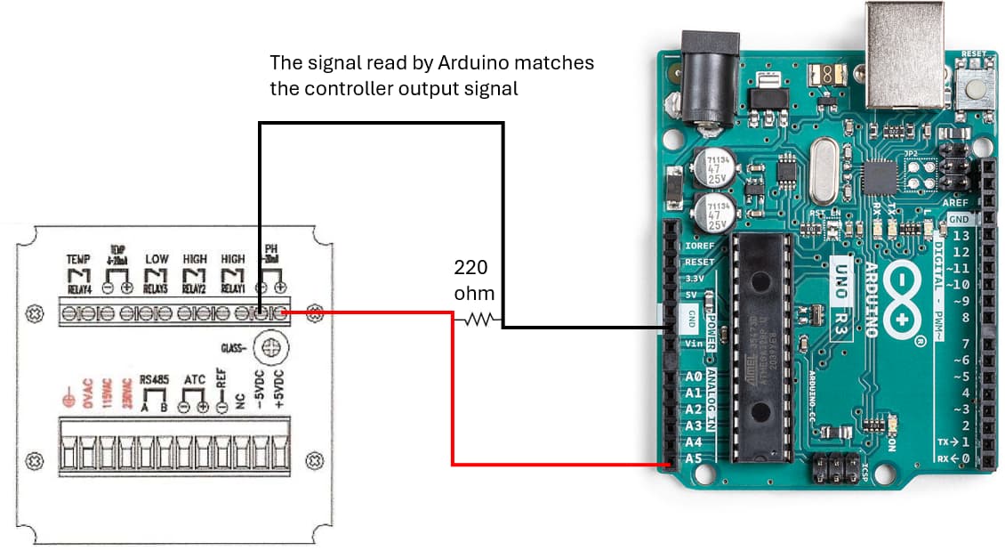
I've wired a single output with a 220ohm resistor between the positive and negative with the positive going to analog pin 0 and the negative going to gnd on the Arduino. This gives me a 0.88 to 4.4V signal to the Arduino. There are no issues here. The pH controller also displays the output signal and it matches what the Arduino reads.
The issue becomes when I wire up the second 4-20mA output the same way I did the first (but to a separate analog input pin on the Arduino). When I wire this second signal in, the Arduino reads the same signal for both pins. I have a feeling I did something wrong on the wiring side of things. Can anyone please provide some advice/assistance?
When people want problems with a device solved, it's helpful to provide a link to the device, or at least a complete part number so we can go look at it ourselves.
Thanks! I think you are right. Do you know of any way I could make this work to read both signals or am I doomed to only be able to read one or the other? I suppose using an couple of if statements with relays could work to turn off and on each signal to the Arduino but that seems like a bit overkill.
Edit: I see you have been modifying the first post. Please do not do that, as it makes the thread nearly impossible to follow.
There is not enough information in the manual linked above to determine how to correctly wire the 4-20 mA outputs. I suggest to get an Arduino RS485 adapter instead.
Sorry, everything I changed was below the "Edit:" text. I just made several quick edits to the code I posted because it didn't format the way I intended (this is my first post on this forum). I'll refrain from editing in the future.
You could use a multimeter continuity check setting to determine whether the negative terminals of the 4-20 mA outputs are internally connected, that is, share a common ground. In such a case there should be no problem with the wiring you originally posted.
There IS a known problem with switching channels on most MCU ADCs, in which one channel reading appears to affect the next channel reading. People solve that by discarding the first ADC reading after changing channels.
Post examples of the problematic output so that forum members have the information needed to provide informed help.
I'm not sure they will be isolated from each other,
so a continuity check between the GNDs would be useful, just to eliminate that posibility.
Also you should protect the arduino with a series resistor (say 20k) to each analog input, and a small capacitor (say 10nF) to reduce noise.
as @TomGeorge says, you need a dummy read of the ADC before taking a valid reading, and I'd also be inclined to add a digital filter as explained here - your temperature and pH readings are unlikely to change very rapidly.
I've connected a multimeter to each analog out negative line and got a 204 ohm reading. It changed when I checked again in 2 hours from turning the unit on to 145 ohm. I guess these signals are not isolated from each other then.
You should NEVER, NEVER measure Ohms in a powered circuit.
Be sure to complete the instrument log-in procedure before doing any tests. ALL!!! the output of the device are generated by the controller in the device, NOT the sensors connected to the controller.
Alright dude, calm down. I'm very new to anything to do with electronics, I just started getting into it in the past 3 weeks. And as for "reading the manual", of course I have read it. Why would I link to it without reading it? Your condescending tones are not appreciated.
Going through the calibration settings does nothing to the output of the controller. The screen of this controller displays the output signals for both temp and pressure - which are different values and match perfectly to the converted voltage signal I read on the Arduino when either ONE is connected:
Controller Display:
pH mA out: 8.29mA
Temp mA out: 7.38mA
Arduino output with the posted code when ONLY pH signal is connected:
T, (floating value),
P, 1.82,
Arduino output with the posted code when ONLY temperature signal is connected:
T, 1.61,
P, (floating value),
When BOTH signals are connected to different analog inputs on the Arduino, both inputs read the average of the two signals:
T, 1.71,
P, 1.71,
These results are the same with and without a "dummy" reading.
Then that tells us the manual is wrong. That happens because the writer of the manual was writing what they though they heard from the engineers, not what they, themselves, observed or tested. Thia is not an unknown problem with manuals on anything!
IS your project requiring both to be shown at the same time, or could one side be opened while the other is read?
Simplest change, then would be to use a DPDT relay, Double pole, double throw. Normal connected to one signal pair and when your Arduino activated the relay, then the other pair is connected. That way your program always knows which signal is being monitored.