The CNC shield disables the steppers by default. Either add code to enable the steppers in software by setting pin 8 to LOW or jumper the enable header to ground.
Here I add the code to enable steppers in software. Additions marked // *****.
#include <MobaTools.h>
const int stepsPerRevolution = 200;                 // number of steps per revolution of the steppers used
MoToStepper MotorX(stepsPerRevolution, STEPDIR);    // create one bipolar stepper using stepper mode, since motor is connected via DRV8825, with 200 steps per revolution
MoToStepper MotorY(stepsPerRevolution, STEPDIR);    // Idem
MoToStepper MotorZ(stepsPerRevolution, STEPDIR);    // Idem
//int limitSwitchY = 10;                              // To later on allocate pin 10 to the limit switch associated with MotorY
//int limitSwitchZ = 11;                              // To later on allocate pin 11 to the limit switch associated with MotorY

const byte stepperEnablePin = 8; // ***** add enable pin

void setup()
{
  pinMode(stepperEnablePin, OUTPUT); // ***** make enable pin an output
  digitalWrite(stepperEnablePin, LOW); // ***** enable steppers

  // ----Constants----
Or by placing a jumper on the EN/ground header. If the Enable pin is grounded, the steppers are permanently enabled. Software control of the enable is no longer possible.
Also, though I have not used it, MobaTools has an enable function, too.
void myStepper.attachEnable( uint8_t pinEna, uint16_t delay, bool active );
This defines a pin which can be used to switch the motor on or off or to set it to power saving
mode. The pin is always active while steps are being output.
pinEna: Arduino pin number.
delay: Delay between pin switch-on and 1st step in ms, also between last step and pin
switch-off.
active: Output active HIGH or active LOW.
With the CNC shield you cannot control the individual motor enables, though. All 4 stepper driver enable pins are tied to pin 8 on the PCB.
Thanks a lot! what's funny is that I bought specifically some jumpers to add one on the EN/GND pin... And forgot in between.
Now I might have some pin issues, because when I power the arduino on, motor z (it seems) do something, like "tick" noises, but none of them move. I'll have a more careful look at the pinout.
Thanks again!
Those are the correct pins for the steppers. Plus pin 8 is enable for all motors, pins 9, 10, 11 are the X, Y, Z limit pins (respectively). Unless spindle speed is enabled. then pins 11 and 12 trade functions. Pin 11 becomes spindle speed (PWM) and pin 12 is Z limit.
Did you make any changes to your code or is it the same, but with my additions. If you do make changes, please post the latest version so that we can keep up.
I think all I did was to make Z rotate in the opposite direction to identify more easily the motors:
#include <MobaTools.h>
const int stepsPerRevolution = 200; // number of steps per revolution of the steppers used
MoToStepper MotorX(stepsPerRevolution, STEPDIR); // create one bipolar stepper using stepper mode, since motor is connected via DRV8825, with 200 steps per revolution
MoToStepper MotorY(stepsPerRevolution, STEPDIR); // Idem
MoToStepper MotorZ(stepsPerRevolution, STEPDIR); // Idem
//int limitSwitchY = 10; // To later on allocate pin 10 to the limit switch associated with MotorY
//int limitSwitchZ = 11; // To later on allocate pin 11 to the limit switch associated with MotorY
void setup() {
// ----Constants----
 MotorX.attach(2,5);                              // STEPpin, DIRpin arccording to CNC shield routing
  MotorY.attach(3,6);                              // Idem
MotorZ.attach(4,7); // Idem
MotorX.setSpeed(600); // Set rotation speed of motor X to 60 rpm
MotorX.setRampLen(50); // Set 50 steps acceleration ramp for MotorX
MotorY.setSpeed(600); // Set rotation speed of motor Y to 60 rpm
MotorY.setRampLen(50); // Set 50 steps acceleration ramp for MotorY
MotorZ.setSpeed(600); // Set rotation speed of motor Z to 60 rpm
MotorZ.setRampLen(50); // Set 50 steps acceleration ramp for MotorZ
//pinMode(limitSwitchY, INPUT); // Set input sense for limitSwitchY (pin 10)
//pinMode(limitSwitchZ, INPUT); // Set input sense for limitSwitchZ (pin 11)
// ----Initialization actions----
MotorX.rotate(1); // MotorX starts to rotate forward continuously
}
void loop() {
// put your main code here, to run repeatedly:
MotorY.write(360);
MotorZ.write(-360);
}
This is not very spectacular, but as soon as I power the arduino on, one can hear one loud continuous motor sound for ~2s, then a 7s silence, then continuous regular tick sounds about one every second or less on MotorZ.
Maybe I damaged drivers for some reason.
Maybe I should test another library like accelstepper to see how it goes?
You're right it makes no difference, following code doesn't work:
#include <AccelStepper.h>
#define dirPin 5
#define stepPin 2
#define motorInterfaceType 1
AccelStepper MotorX = AccelStepper(motorInterfaceType, stepPin, dirPin);    // create an instance of accepstepper class for X motor with CNC shield

void setup() {
  MotorX.setMaxSpeed(200);                                                  // set max motor speed to 200 steps per second
  MotorX.setAcceleration(30);                                               // set acceleration to 30 steps per second per second
}

void loop() {
  MotorX.moveTo(600);                                                       // target position
  MotorX.runToPosition();                                                   // command to go to position
  delay(1000);                                                              // 1s pause
  MotorX.moveTo(0);                                                         // set target to initial position
  MotorX.runToPosition();                                                   // command to go to position
  delay(1000);                                                              // 1s pause
}
Did I fry the drivers then? Is there a way to test them?
I do not see anything wrong with the code, but i am on my phone so can't test it.
I will set up my Uno and CNC shield so that i can test your code in a while. I can't just now.
So you hear those noises, but none of the motors move? Is that right? Or is it jit the Z motor that will not move?
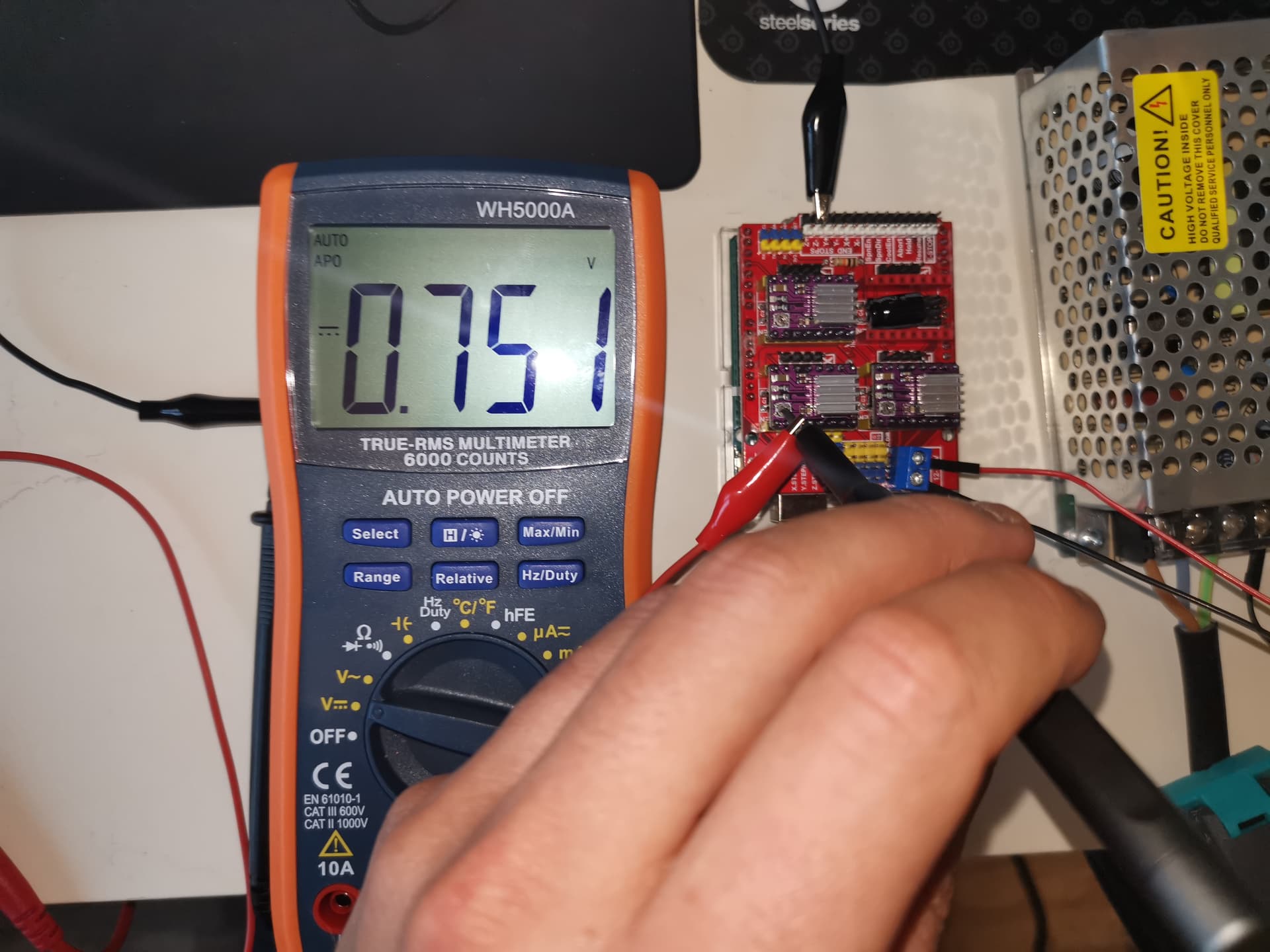
Please refresh my memory. You did, properly, set the DRV8825 coil current limits? If so, what value of Vref?
The fastest and surest way to kill a stepper driver is to connect or disconnect the motor from the driver while the motor power is energized. It only takes a millisecond.
I will fire up my system and give your code a try in a bit. And I can post some known good test code.
Nice to hear that. At least I know I can use this once I'll figure out what's wrong with the Hardware.
Yes correct, none of the motors move. Maybe the Z one move one step per one step while ticking. I can't tell.
Yes I took a value of Vref = 0.95 V (my motor being 2A). I'll check it again once at home, maybe I didn't really pay attention and in fact it was 0.95 mV.
I do not remind doing such a thing. I plugged motors when everything was off, and let them plugged afterward.
That is running the driver pretty near their max current spec. I have read that the heat sinks on the DRV8825 drivers are not particularly effective without active (fan) cooling. I would suggest that you drop the current limit to no more than 1.5A unless you use a fan.
It is a good idea to not use more current than is necessary to get good performance with no missing steps. The motors and drivers will run cooler and live longer.
Yes, that is the correct jumper placement to permanently enable the stepper driver outputs.
Surprisingly, now when I play the code with Moba Tools, not only the Z motor ticks, but so do the 2 others...
Is there any chance that it could end up working by fine tuning Vref?
I ordered another CNC shield from elecrow. Not that I saw something wrong on the first one, but who knows. I also ordered some spare drv8825 from aliexpress. Then I guess I'll try to replace parts one by one until it works.
Yes I will try to experiment a little waiting for the spare boards.
I have to figure out who's to blame beween arduino, CNC shield, motor drivers, 12V power suppply, or me.
Guess I can start by testing the arduino and the power supply, those are easier.
Only had one bad Chinese board and that was a MEGA that had clearly been broken before sending and had a crack across it. Got my money back no problem.
Have used a lot of different suppliers for the CNC shield and not on of those has been bad.
Not to say there "might" be some bad ones but difficult to believe as they all tend to use the same thing.
Motor drivers can be a slightly different matter but the only ones that have failed me were ones where I was at fault and either inserted into the board wrongly or cranked the adjustment without a multimeter. Also had one where the heatsink touched two pins so now I only use superglue to mount them. Double check on the internet for mounting you particular drivers as there is a lot of good info out there and some boards have the adjustment pot in different locations. They do not always mount in the same direction.
Always check the A!1,A2,B1.B2 and they always go closest to the motor connection.
Also hard to get the PSU wrong as both the PSU and the shield are marked quite well.
I actually tin the wires so there can never be any stray ones !
Maybe this could be an explaination. First, I used wires with dupont connectors that I screwed directly into the shield connector. And second, the screw on the - side of the connector on the CNC shield is blocked, so that it is kind of loose compared to the +.