Long story short, what I'm looking to do is to automate a chop saw for brass. This is my very first project and I don't have any background in electronics.
I have a more generic topic here about the project in itself: 1st project guidance: mini chop saw automation (with CNC shield)
I have an arduino uno and a CNC shield with DRV8825 drivers that I'll use on Nema 17. I don't think I'll use GRBL for programmation, but I'll see when I'll be there.
I will use 3 endstops (I don't know yet if I'll use optical or mechanical ones), and 3 inductive proximity sensors.
My issue is that I have no idea how to connect them to the CNC shield...
In the other topic I reported the state of my research from day to day.
Any resource you could share?
Hi Railroader, you mean regarding my project or wiring of the endstops?
Regarding the project (I will take a picture this weekend) so far:
I plugged the cnc shield on arduino
I plugged 3 drivers on the shield
I wired the 3 nema 17 steppers
What I need to do now:
Receive my 12v power supply and wire it to cnc shield
figure out how to wire optical endstops on the cnc shield and do it
figure out how to wire inductive proximity sensors and do it
write down the code (i started pseudo code but then I realized you can't do multitasking without doing tight loops, so I'm trying to figure out how I can using millis() or micros() with my steppers)
extra bonus 1: look how I can integrate a lcd screen and a button for very basic commands (start, pause, resume, stop)
Extra bonus 2: look how I can add a relay to start and stop the saw
do the mechanical design
If you mean about wiring the endstop if I tryed something, not yet, waiting the power supply to come to power up the shield. But I could remove the shield and experiment with the arduino itself and the serial console to see if I figured out the pins correctly, and then mimick the pin scheme on the cnc shield later on.
Regarding the code, I have only pseudocode so far, but I just realized I needed to use millis() for multitasking so I have to change everything.
I'll add a first attempt of code this weekend (in the global project topic also)
Get hold of the pin usage of the shield You have told nothing about.
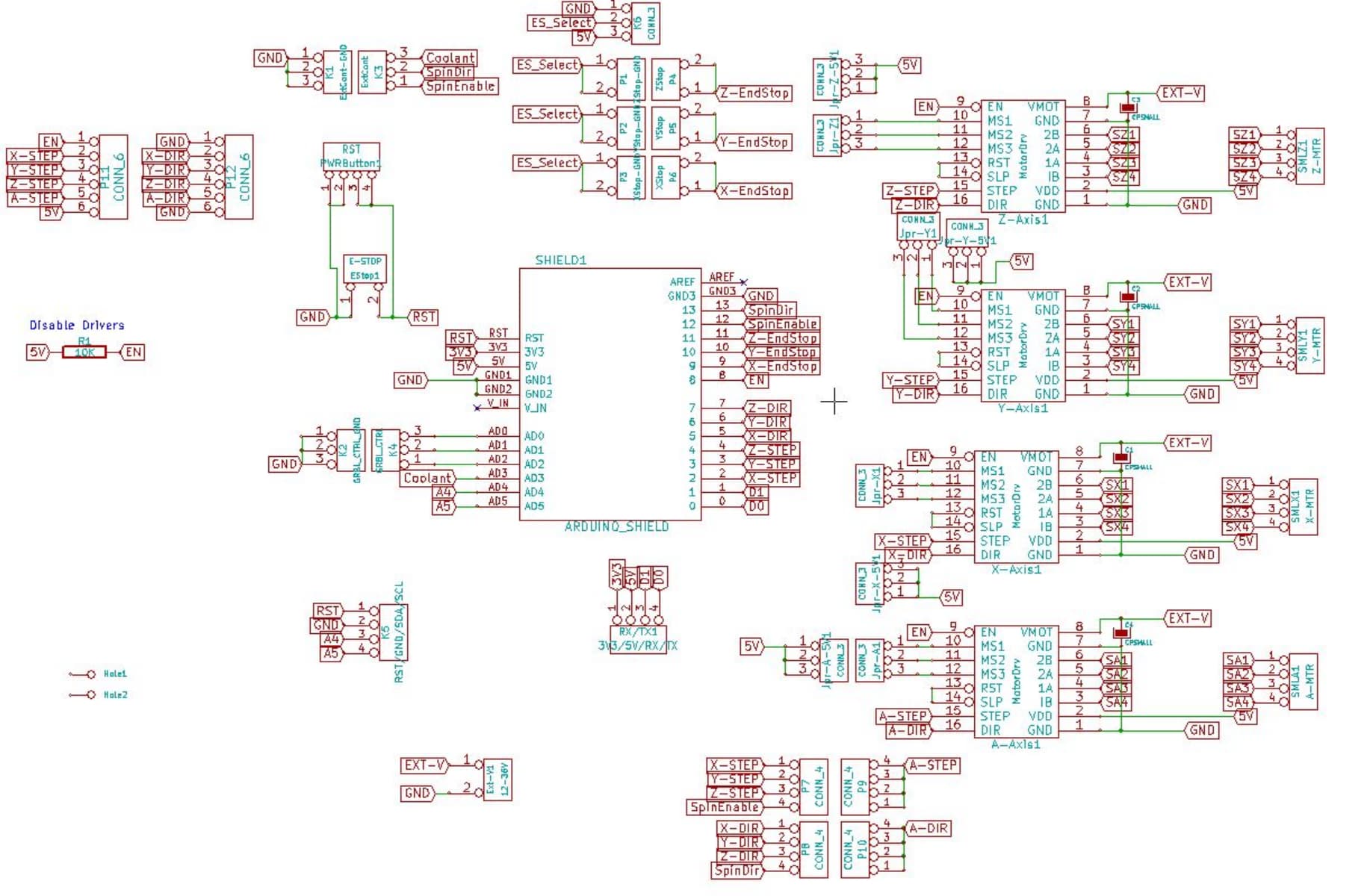
In a commonly used CNC shield v3 from Prootooner there are inputs for end switches, if it is that shield.
For the CNC shield V3 here is the pin mapping of the shield to an Uno. If you have used the X, Y and Z limit pins (pins 9, 10, 11) there are still pins 12 and 13 and the analog input pins. The analog input pins are really digital pins with analog input as a special purpose of analog input so you can use them for digital IO. Those pins have internal pullups, too.
Make sure that you set the coil current limits on the DRV8825 drivers. That is important. See the Pololu DRV8825 driver page for instructions.
For a display, the I2C pins (A4 and A5) are broken out on the shield. So a 1602 or 2004 I2C enabled display is easy to connect. Use the hd44780 library to control the display.
It is not exactly what I expected, thought it wouldn't have required extra components and bread board. But hey it is what it is ! What exactly is this PC817?
And about the optical endstops, they are blasini optical endstops, the same than the ones found in here: optical-endstop-for-3d-printer-cnc-robotics
I don't have more info than:
Are you going to write your own code for the steppers? If you are going to want very much speed from your steppers, you will need acceleration (steppers cant go from 0 to high speed without acceleration). I like the MobaTools stepper library. It features non-blocking functions for motion and acceleration and, I think, is easier to learn and use than, say, Accelstepper. MobsTools is available for installation via the IDE library manager.
I will need to study the proximity sensor. I don't have time right now. What is the reason for using that particular sensor?
That is an optical coupler to electrically isolate the (9V) sensor from the (5V) Arduino.
The opto sensor wiring looks good. Enable the internal pullup on the Z axis limit pin (digital pin 12 for the grbl-Mega firmware) or supply and external pullup. The opto is usually open collector, that is why it needs a pullup.
I thought I have to because I need to do several tasks in parallel. I have 3 motors. Here are the 2 main tasks:
task1: Motor 1 runs as long as proximity sensor1 is not activated (casefeeder motor that stops whenfeeding tube is full)
task2: Motor 2 and motor 3 do a coordinated cycle in parallel of task 1. motor 1 does one rotation (to feed the cutting guide), then it stops and motor 2 does une rotation (activate the saw), and task2 starts again.
But reading this:
and by checking the documentation of the library, where I can read:
The program in the 'loop' continues to run while the stepper motor is
turning.
I suppose I have to think a little bit if there aren't some easier ways to do what I want.
They are suitable for copper and it seems they also work with brass. But there are no particular reason out of this one, except maybe that I saw some people used it for arduino projects.
OK got it thanks
Since I won't use grbl, can I do that on the pin 11 of the arduino. Do you mean I should be adding this to the code?
It's not that difficult. The logic, checking sensors, buttons etc. in loop can use boolean flags telling different activities to Go, Stop, Sleep, drink coffee....
Take a look at the topic "do many things at the same time"! It shows a principle that applies to Your project as far as I can see.
Which seems tricky to me is to handle stepper movement in a tight loop. I imagine you can say if millis()-previousmillis() > X then move 1 step or something like that, but then won't it be "jerky"? In case MobaTools doesn't allow me to do what I want, I'll experiment with millis() (or micros() depending the speed I want to achieve).
I haven't used MobaTools yet, only some little AccelStepper. It's worth investigating MobaTools. If the library uses a hardware timer it shouldn't be jerky.
Maybe @groundFungus knows what happens "behind the stage".
MobaTools and Accelstepper both do stepping in the "background". The difference is that in MobaTools one does not have to call a function (run()) for each step.
OK I'll keep that in mind. I'll first try a loop with MobaTools, see if I can achieve parallelization as I expect.
Then if really I can't do what I want, I'll check the direct method with Robin2's tutorial. Thanks.
I'll post my code in the general thread I think more than in this one where I specifically addressed wiring.
I'm not very familiar with optical coupler (and electronics in general), so I have a naive question regarding this schematic.
Since I have a 12V power supply in my system, I'd rather use it than add 9V.
Can I keep the same setup? Maybe I have to change the 1 kOhm resistance for something like 1350 kOhm, am I right?
I wanted to experiment a little with MobaTools. Wired the arduino, CNC shield, drivers (I setup Vref according to tutorials), external power supply, and steppers like this:
// --------------PROJECT DESCRIPTION--------------
// An arduino UNO with a CNC shield V3 using 3 DRV8825 drivers are used to drive 3 Nema17 stepper motors
// MotorX runs continuously
// MotorY runs for one turn, then stops
// MotorZ runs for one turn, then stops, then the Y / Z cycle starts again
// see https://github.com/MicroBahner/MobaTools for more details about MobaTools
// -----------------------------------------------

#include <MobaTools.h>
const int stepsPerRevolution = 200;                 // number of steps per revolution of the steppers used
MoToStepper MotorX(stepsPerRevolution, STEPDIR);    // create one bipolar stepper using stepper mode, since motor is connected via DRV8825, with 200 steps per revolution
MoToStepper MotorY(stepsPerRevolution, STEPDIR);    // Idem
MoToStepper MotorZ(stepsPerRevolution, STEPDIR);    // Idem
//int limitSwitchY = 10;                              // To later on allocate pin 10 to the limit switch associated with MotorY
//int limitSwitchZ = 11;                              // To later on allocate pin 11 to the limit switch associated with MotorY

void setup() {
  // ----Constants----
  MotorX.attach(2,5);                              // STEPpin, DIRpin arccording to CNC shield routing
  MotorY.attach(3,6);                              // Idem
  MotorZ.attach(4,7);                              // Idem
  MotorX.setSpeed(600);                            // Set rotation speed of motor X to 60 rpm
  MotorX.setRampLen(50);                           // Set 50 steps acceleration ramp for MotorX
  MotorY.setSpeed(600);                            // Set rotation speed of motor Y to 60 rpm
  MotorY.setRampLen(50);                           // Set 50 steps acceleration ramp for MotorY
  MotorZ.setSpeed(600);                            // Set rotation speed of motor Z to 60 rpm
  MotorZ.setRampLen(50);                           // Set 50 steps acceleration ramp for MotorZ
  //pinMode(limitSwitchY, INPUT);                   // Set input sense for limitSwitchY (pin 10)
  //pinMode(limitSwitchZ, INPUT);                   // Set input sense for limitSwitchZ (pin 11)

  // ----Initialization actions----
  MotorX.rotate(1);                                // MotorX starts to rotate forward continuously
}

void loop() {
  // put your main code here, to run repeatedly:
  MotorY.write(360);
  MotorZ.write(-360);
}
The motors do not move at all. I don't really know where to start for investigations. Any hint?
Note: I know that with MobaTools MotorY and MotorZ are not expected to rotate sequentially contrary to what I wrote in the header of my code, but I just wanted to see things move before doing more code.