I have an SMC ISE20A-T-P pressure switch that my team is using for our mech. eng. senior design project. I want to take the outputs from this switch and send them to an arduino for further processing. The input requirements are 12-24VDC, and I have the sensor's positive and negative leads connected to a 12VDC power supply. The manual states that it outputs 0-5VDC. There are three output wires. Outputs 1 and 2 are labeled "PNP80mA", while the third output is an analog "Function". I guess my question is which output do I connect to the arduino (arduino uno 3) and how do I go about doing that? My experience with wiring is very limited so please be gentle.


Assume supply is 12v.
-
Place a 1k resistor from grey to negative blue.
-
Measure the voltage across this resistor, what range in voltage do you see ?
-
Place a 330R resistor from black to negative blue.
-
Measure the voltage across this resistor, what range in voltage do you see ?
-
Place a 330R resistor from white to negative blue.
-
Measure the voltage across this resistor, what range in voltage do you see ?
A PNP (switch) output in HIGH state reflects the supply voltage - don't use it with an Arduino of lower Vcc.
The analog T output is fine with short distance between sensor and Arduino, sensitive to environmental noise.
A 4 to 20 mA output (V) is fine with long wires. Add a load resistor that converts the max current (20 mA) to the max acceptable analog input voltage. A broken wire or detached sensor can be detected by measuring zero current instead of the min. 4 mA.
You can safely use the PNP outputs with a voltage divider (10K and 5K) to reduce the 12V output to 4V, which is OK for a 5V Arduino like the Uno. Or, use the 0-5V analog output, and read the voltage with the analog input on a 5V Arduino.
A voltage divider would also be necessary on the analog input of a 3.3V Arduino.
Before connecting the Arduino, use a multimeter to verify that the voltages of the sensor output (with voltage divider) never exceed the Arduino supply voltage.
If you can get the same switch with an open collector NPN option, that is better for interfacing with Arduino.
Depends on what you want. Powering from a 12 VDC supply the max load on the analog out is 300 Ohms and the Analog out is a 4 to 20 mA current loop proportional to the applied pressure. So if I use a 250 Ohm 1% resistor as a load my voltage will be 1.0 to 5.0 Volts. You can map that in your code to derive the applied pressure. What exactly is the intended application?
Ron
But you risk the Arduino if somebody happens to use a 24V PSU with the sensor. Not a good nor safe advice for a newbie, IMO.
I clearly stated 12V, but you have now warned the OP about a possible problem created by someone else, so thanks!
I would consider isolating the Arduino digital inputs with optoisolators.
The T in the part number indicates it's analog output (0.6v - 5V). His model does not have the current loop option.
Thanks for the info. Here are some pics of what I've thrown together: sensor wiring - Album on Imgur
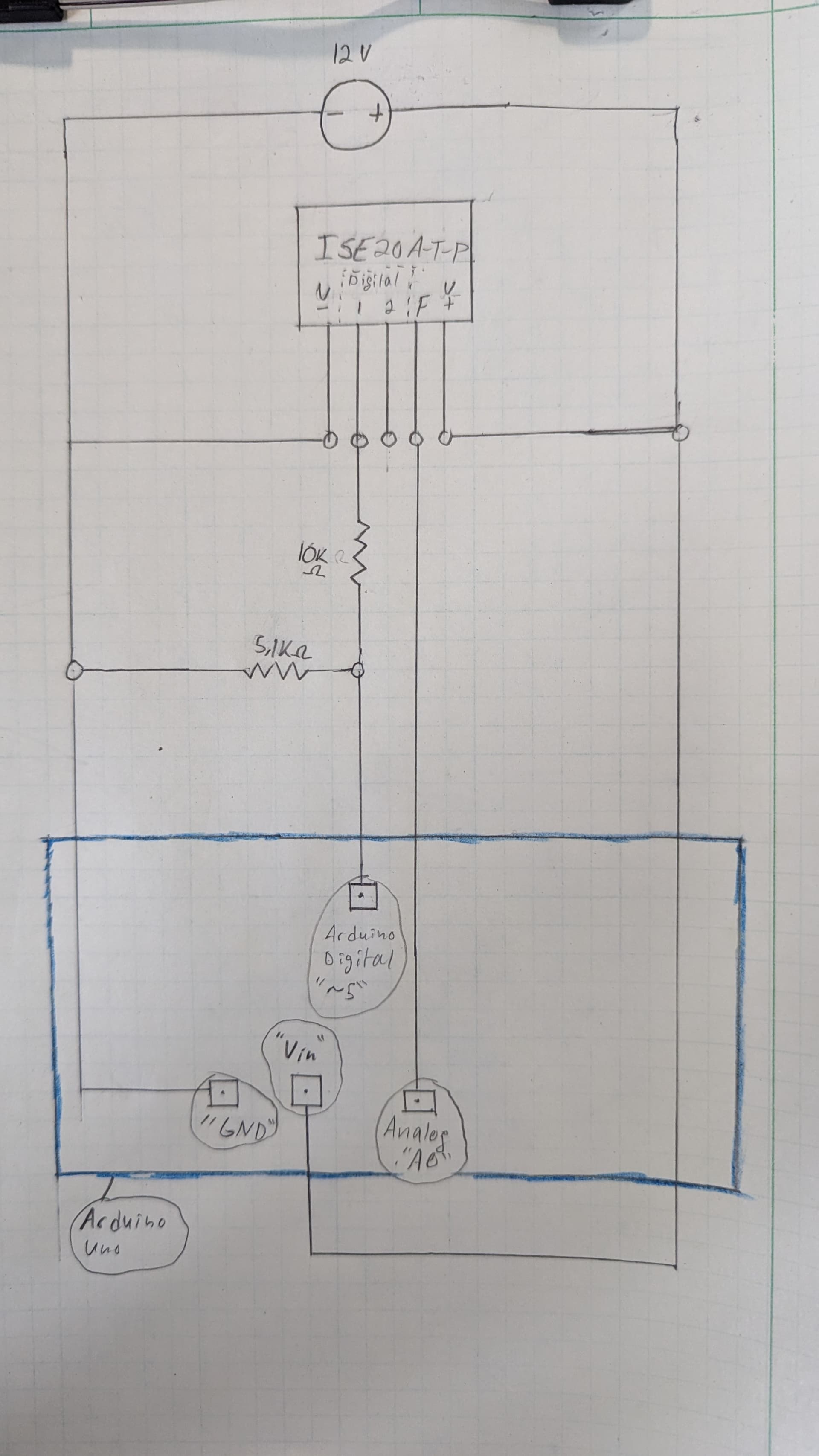
Does this seem right? I was originally planning on running the arduino off USB but now I think it should use the same 12VDC as the sensor, connected to the Vin pin. Is that correct? I have not checked any of the connections yet with a multimeter and won't have the opportunity until after thanksgiving break and I don't plan on powering anything on until then. Let me know if you think this will blow up or not.
Please post a pic of a hand drawn wiring diagram directly in your post. Be sure to clearly label pins and connections.
Breadboards are for short term experiments with low power logic and are not reliable. Do not use them for any sort of long term or semi-permanent installation.
That will burn more energy in the on-board 5V regulator than in the Arduino itself. Better use a 12V to 5V step down converter to power the Arduino.
Analog inputs should be protected using a 10K series resistor, just in case the input voltage exceeds 5V.
I second the recommendation to use a 5V stepdown converter to power the Arduino via the 5V pin, rather that 12V on Vin. This is the one I use.