안녕하세요 저는 한국에서 공부중인 대학생입니다. 다름이 아니라 저희가 압력계를 통해 압력을 실시간으로 측정하고, 이를 통해 압력을 제어하는 장치를 설계하고있는데 압력계와 아두이노를 연결하여 데이터를 받으려 해도 전압과 전류가 매우 낮게 나오는 현상이 발생하여 문의를 드리고자 합니다.
정확한 배선 또한 이쪽 전공이 아니다 보니 제대로 못한것같아 사진에 나온 배선도와 아두이노를 어떻게 연결하여야 하는지 알려주시면 정말 감사하겠습니다. 감사합니다.
Translated --
Hello, I am a college student studying in Korea. The reason is that we are designing a device that measures pressure in real time using a pressure gauge and controls the pressure through this. When I try to connect the pressure gauge and Arduino to receive data, the voltage and current are very low, so I would like to contact you. Since I am not an expert in this field, I think I did not do the wiring properly. If you could tell me how to connect the wiring diagram in the photo and Arduino, I would really appreciate it. Thank you.
Oh, I posted it wrong in Korean. Sorry, thank you for the translation.
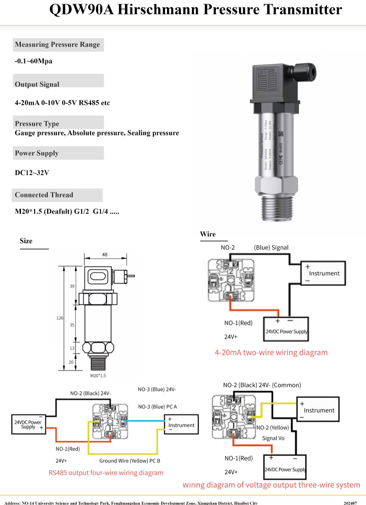
What is the power supply voltage to the pressure transducer?
Which Arduino (or other "compatible" MCU board) are you using?
Do you really want to measure pressures up to 60MPa = 600Bar?
The output at atmospheric pressure is going to very low for that sensor.
The power supply voltage of the pressure transducer is shown as 24V DC. I'm using Arduino Uno.
Yes, the pressure we are trying to measure will actually be 4MPa. However, this is the pressure sensor I already purchased, and I don't have time to buy another one
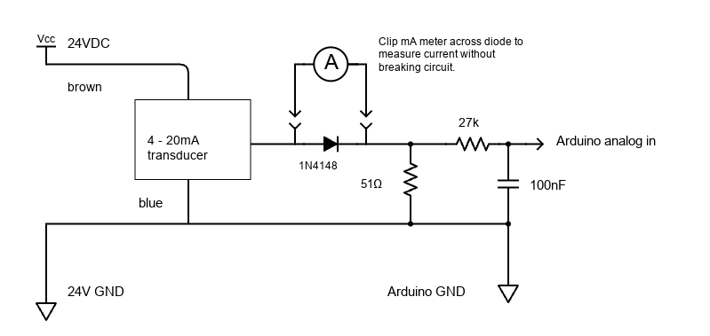
If you use the 4-20mA output, this module can handle the job for you. You can find more information here: Arduino 4-20mA Current Loop Receiver Shield.
However, this may not fully address your question, as you haven’t specified which port or interface you want to use. Please provide more details so we can guide you better!

Use a 51Ω load resistor for the sensor and set analog reference to INTERNAL in setup().
analogReference(INTERNAL);
and connect like this:
1 Like
Oh, I couldn't tell you more details. Currently, there is no 24V power supply, so we plan to supply power to the pressure converter using Arduino and 24V boost converter. Also, I don't have a capacitor, so I want to know if there is another way.
We would like to receive the information of the pressure converter through Arduino's analog port. The interface is difficult to answer because I don't know exactly, but I think I will use general serial communication.
According to your link, the sensor will work on 12V. If you use 12V you could reduce the 27k resistor to 15k. The cap is for stabilizing the input and bypassing noise, you may be OK without it.
Oh, so I don't use the capacitor, can I change it to 15k ohm after changing it to 12V output? As mentioned before, I want to receive 12V output from the same Arduino through the converter, how should I change the wiring of it? I'm so sorry for the late hour
Also for the diode, the only product I have is 1N4007 1000V, is it okay to use this instead? Or is there a way to not use it at all?
You just totally confused me, post a wiring diagram of your project.
1 Like
That would work but it's not actually needed. It's just a trick to enable testing current without breaking the circuit.
It's a wiring diagram that I drew in my own way through Chatgpt. I'm so sorry for the inaccurate explanation because I'm not a major here.
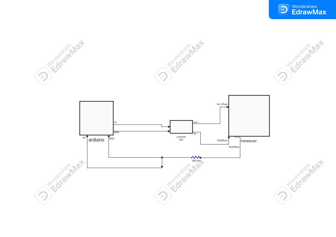
That drawing makes NO sense, you have A0 connected to GND.
Maybe one of the other forum members can help.
1 Like
If so, I will refer to the wiring diagram you made and make it. Could you please provide power to the transducer through the 24V converter and other Arduino, and draw a new wiring diagram that does not use diodes and capacitors? In addition, the existing wiring map extends in three directions to the transducer, and I would like to know if you can write down the No of each part Thank you.
1 Like
This topic was automatically closed 180 days after the last reply. New replies are no longer allowed.