MC14511B
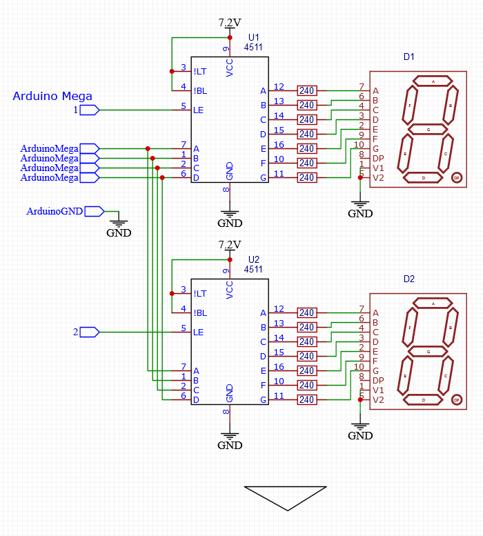
The schematic I show in post #5 is correct.
Vcc = 12V
Do Not connect anything to COM
Works with the SevSeg lib
Seems like many people still don't understand how an LED works.
Yes you should.
First things first, a seven segment display that requires 7.2V is something I have never come across before. Where did you get that figure from. Given your other errors mistaking absolute values for working values, I suspect you have done the same here.
Can you post a link to the data sheet or to where you got this device from that mentioned this figure.
Assuming that this 7.2V requirement is a mistake, the the best way is to use a MAX7219 display driver for each 8 digit display you have. The big advantage of this chip is that it handles the decoding, current limiting and the multiplexing in a set and forget way and saves a whole heap of processing time as well as code complexity.
The MAX7219 should be driven by the SPI interface on your Arduino and you can chain many chips, or use an individual chip enable for each device.
Look up the data sheet of this device to see what it can do. There are also libraries to help you if you can't understand how to address the chip directly, as it could seem daunting to a beginner.
It appears to be a large format display, where each segment has 4 pairs of LEDs in series. So 1.8V * 4 = 7.2V
As well as the usual Chinese sales channels, apparently Walmart sell them !
Unable to find a datasheet.
Try reading post #9
1 Like
Specification
Light Color: Red
Model: FJS30101AH-4
Package Type: Plug-in
Common Pin: 1&5
Voltage: 7.2 V
Pin Count: 10
Number of Characters: 1 Bit
Common Type: Common Cathode
Character Height: 1.5 inch
Size: 65 x 86 x 12 mm / 2.6 x 3.4 x 0.5 inch (LWH)
Packing List: 2 x LED Display Digital Tube
Thanks @jim-p . I have sourced the components and will give this a go and report back with my results using this schematic as a starting point.

The parts you soured from Mouser are the correct ones.
Have a nice day!
Earlier, you mentioned
That is not mentioned above, where did you get that figure?
If @bobcousins has correctly identified your digits, then the max current could be closer to 40mA.
Walmart are providing an eCommerce market place for 3rd party suppliers, just like Amazon do. You won't find this product in a Walmart store.
Make sure you check the pinout on your particular displays
The ones I used in my schematic were just some Generic displays and the pinout may not be the same as the ones you have.
Hmmm... It appears I pulled that from the wrong spec sheet. If the consensus says it is closer to 40 mAmps then:
@jim-p > They put 4 LEDs in series for each segment. So if the nominal forward voltage of each LED is 1.8V, then 1.8V x 4 = 7.2V. So just treat it as a single 7.2V LED.
Resistor value = (12V-7.2V)/40mA :lying_face: = 120 ohms
@PaulRB I found this additional information on the display which seems to confirm the 4 leds per segment. Also gives me the pinouts (common are pins 1&5 for my future reference). On top of this circuit is "1.5". What does that mean?
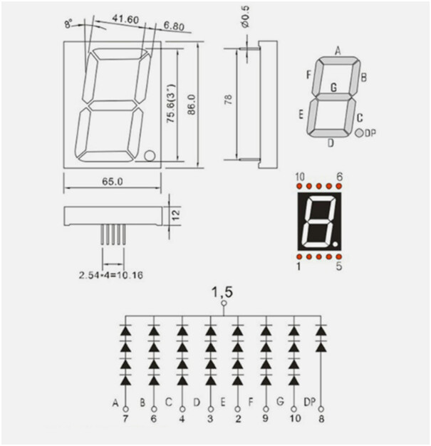
I googled the part number and came up with the same diagram you show.
I would stick with the 240 ohm resistor and 20mA
So the pinouts are different from my schematic
That's 1,5 (1 comma 5) means pins 1 and 5
OK so I have confirmed the game plan and will stick with the most recent wiring schematic with the exception of correcting the pinouts. I just ordered the parts which should arrive in a few days so I'll do the physical wiring next weekend. Thanks to you and the others for all the help.
Make sure you come back and post a picture of your working circuit.
Fair enough, but if you want to learn more about shift registers, there are more types to consider than the classic 74hc595.
There is tpic6b595, which is like a 74hc595 and TBD62084 combined into a single chip. Unfortunately there isn't a chip which combines 74hc595 and TBD62783 into a single chip (unless someone knows better).
Max7219 has also been suggested. It can only drive displays up to 5V by itself, but it may be possible to use it in combination with TBD62084 and TBD62783 for your displays. The advantage of the max chip is that it performs the multiplexing in hardware, relieving your code of that burden. Even with the 7seg library, if you don't write the rest of your code in just the correct way, there is danger of blanking, flickering and uneven digit brightness.
Are you suggesting something along the lines of this is possible? Could the Max7219 be in series with the TBD62783A and take the place of the TBD62084?

No, I did not say that. I said
You could use the 7219.
I didn't suggest it because it cost $12 USD and you still need the other ICs
It can also be done with about 22 transistors if you want something to do.