Machine Hacking: Alginate Bioyarn Extruder - Catherine Euale I have this which trying to make, seems like the code wrong so adjusted a bit , I can upload that as well but the main issue the stepper motor won't start at all. I have tried the simple examples code from Arduino Ide but same issue,so maybe something else the issue. What should know:
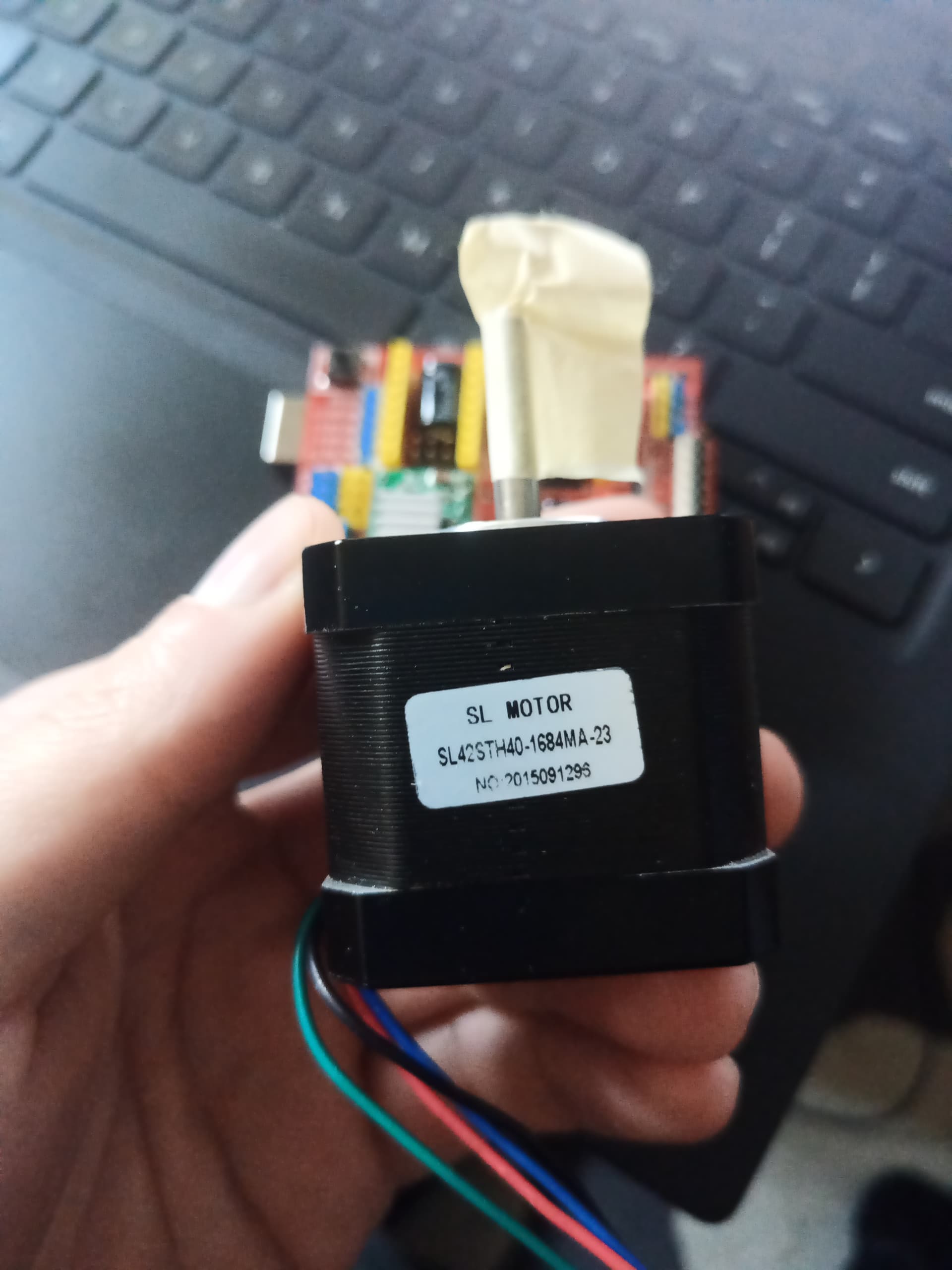
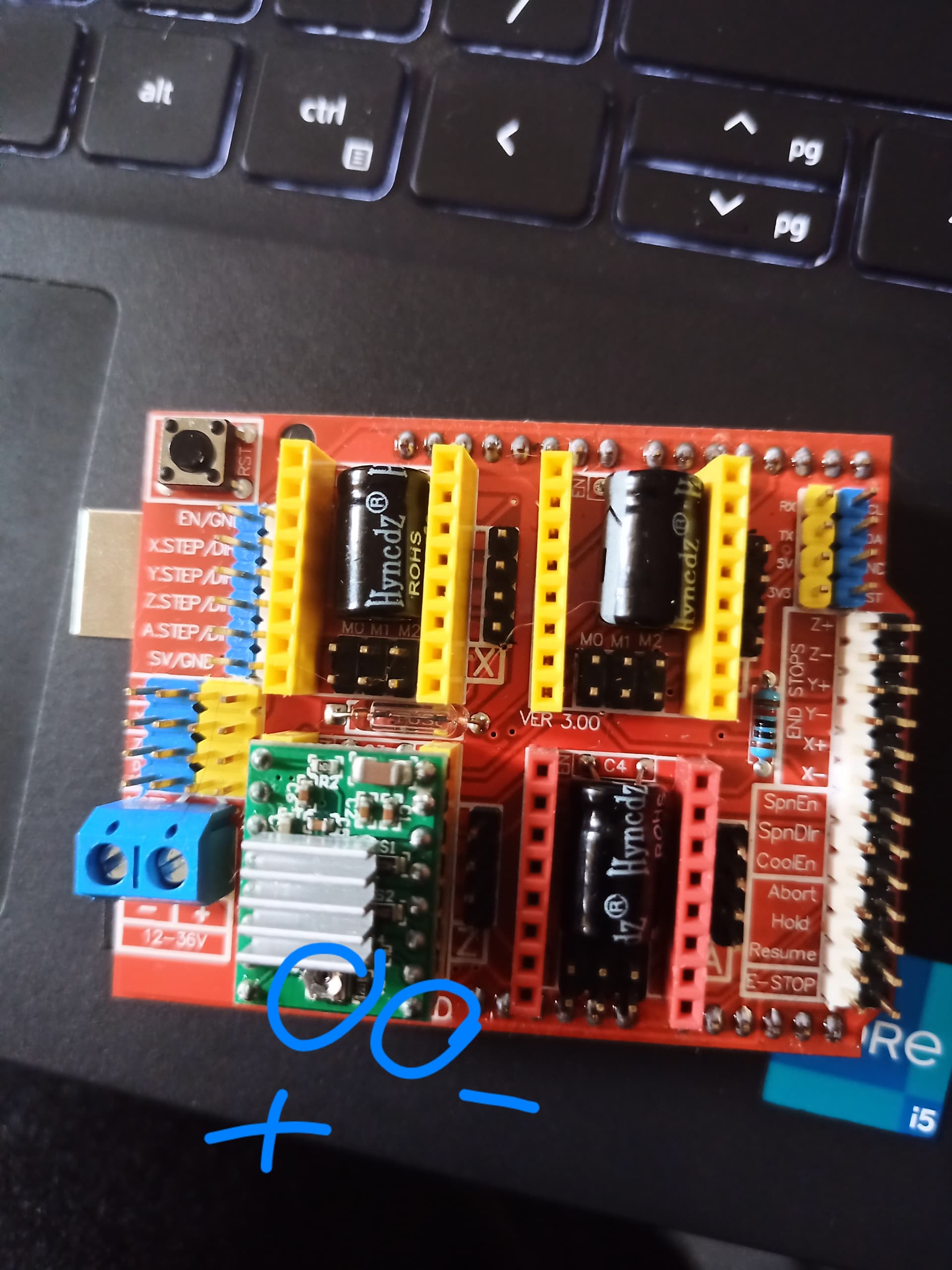
Arduino Uno R3 board , using CNC shield to connect the stepper motor which is NEMA 17 ,and there is a driver to control the stepper motor on top of the CNC shield. Could you please assist why the stepper motor won't start? The V settled for 1.5V (based on calculations find it online)
I much appreciate all of your help.
Lots of reasons are possible:-
Inadequate power supply.
Incorrect setting of the motor voltage.
Trying to go too fast
Need to swap over one of the motor's phase windings.
Thanks for the answer. Here is the code,to be honest I'm still learning coding so basically new .
#include <Arduino.h>

/* MotorCode by
Ioannis Romanos Vogdanis
for ceramic extruder
February 2019

To control the motor open the serial monitor and set the BAUD rate at 115200 (bottom right) and no line ending.
The keyboard keys “
v , s , f , b are used to send commands to the motor.
v = velocity range from 10 - 2000;
s = start/stop the motor
f = forward
b = backward
*/

// Pin definitions
const int enablePin = 8;
const int dirPin = 5;
const int stepPin = 2;
const int ms1 = 8;
const int ms2 = 9;
const int ms3 = 10;

// Variables for motor control
bool start = false;
bool dir = false;
bool enableMot = false;
int mspeed = 1000; // Default speed in microseconds

void setup() {
  // Initialize serial communication
  Serial.begin(115200);

  // Initialize pin modes
  pinMode(13, OUTPUT);
  pinMode(enablePin, OUTPUT);
  pinMode(dirPin, OUTPUT);
  pinMode(stepPin, OUTPUT);
  pinMode(ms1, OUTPUT);
  pinMode(ms2, OUTPUT);
  pinMode(ms3, OUTPUT);

  // Initialize motor state
  digitalWrite(enablePin, HIGH); // Disable motor initially
  Serial.println("---Paste Extruder---");
}

void loop() {
  // Check for serial input
  if (Serial.available() > 0) {
    char c = Serial.read();
    runCommand(c);
  }

  motorControl();
}

void runCommand(char c) {
  switch (c) {
    case 's':
      start = !start;
      Serial.print("Start : "); Serial.println(start);
      break;
    case 'f':
      dir = true;
      Serial.println("Dir forward");
      break;
    case 'b':
      dir = false;
      Serial.println("Dir backward");
      break;
    case 'e':
      enableMot = !enableMot;
      digitalWrite(enablePin, enableMot ? LOW : HIGH);
      Serial.print("EnableMot : "); Serial.println(enableMot);
      break;
    case 'v':
      Serial.println("Set speed (10-10000 microseconds per step):");
      while (Serial.available() == 0) {
        // Wait for user input
      }
      mspeed = Serial.parseInt();
      Serial.print("Setting speed : "); Serial.println(mspeed);
      break;
    default:
      Serial.println("Invalid command");
      break;
  }
}

void motorControl() {
  if (start && enableMot) {
    digitalWrite(dirPin, dir);
    digitalWrite(stepPin, HIGH);
    delayMicroseconds(mspeed);
    digitalWrite(stepPin, LOW);
    delayMicroseconds(mspeed);
  } else {
    digitalWrite(stepPin, LOW);
  }
}
This is which reworked but also tried a simple just running code. The power supply goes directly to the board which is a AC/DC 12 V adapter. The driver has been changed to 1.2V based on internet searches.
Thank you StefanL38 for the answer. The driver A4988 current limit of the reference voltage. Reworked means when first checked the original code which link provided in the beginning of the post there was lot of error.
The red (positive) connected to the part where you can change the reference voltage and the black (negative) to the first pin next to this reference voltage "button" . It was tried between 0.6-1.5 V no luck. Based on calculations it should be 1.2V if the informations are correct from the web.
never ever connect / disconnect the stepper-motor-wires when power-supply is switched on
stepper-motor-coils are inductive loads that create high voltage-spikes when disconnecting the motorwires while current is flowing through the motorwires.
It is almost the same as an electric fence. These high-voltage-spikes can damage the stepper-driver.
Whenever you want to connect / disconnect the stepper-motor-wires switch off the power-supply
I am happy to give more information but because this is the first time using this I don't have much experience, so please ask and I will answer for all questions.
The driver-board has an enable input. Did you connect the enable-input with the correct voltage according to the datasheet of the A4988-stepper-driver?
did you connect ground from motorshield with ground of which exact type of microcontroller?
Didi you check with a serial resistor and an led if the outputs you are using is creating a signal at all?
GND---470 -Ohm-resistor----LED-----IO-pin
can your multimeter measure frequency?
if yes measure the frequency on the step-pin while the code is creating step-pulses
A stepping motor has two coils to drive it. There is no universal way to decide the phase of these coils. If this is wired wrong you can have the motor fighting itself and so will not move but will sort of buzz. So to check if this is happening then, swap over the wires driving one of these coils.