I am trying to get the electronics part of my diy cnc to work together, however, after researching and trying things for few hours (it's 4:30am), I just don't know.
I am new at arduino, only played around with it so far. The reason for thinking that I have a defective cnc shield is that about a quarter of the pins were bent and "barely" 2 of the 4 drivers "seem to" work or at least gives a voltage.
17HD48002H-22B Nema 17 Steppers
Step angle: 1.8°
Holding torque: 59Ncm (84 oz.in)
Rated current / phase: 1.7A
12v 5A Power Supply
I am trying to get ONE stepper to move right now.
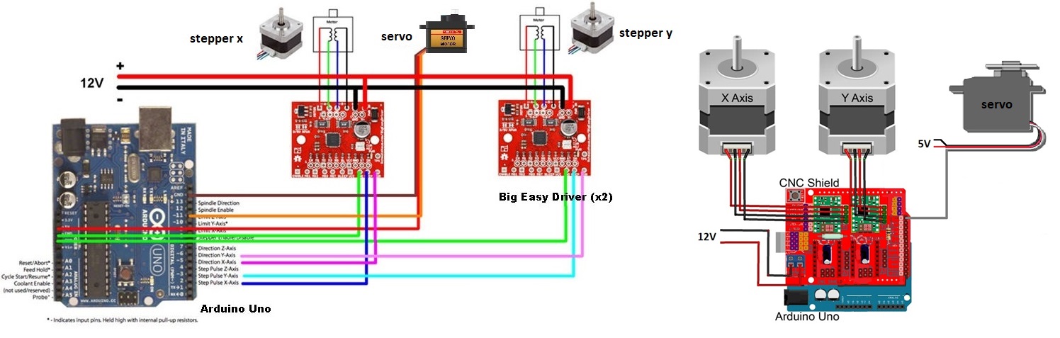
I have the cnc shield connected to the arduino, driver plugged to the X slot on the shield (en pin next to reset button).
I have 4 drivers, one seems to work normal (the one I am using for my tests, set from 0.3 to 0.75v as I was testing things), one only goes up to 0.32v and the other 2 stay at 0.0v, the good one works on all four slots on the shield, same thing for the 0.32vref driver (so guessing I have 2 dead and 1 malfunctioning).
I uploaded grbl 1.1 without problem, arduino is working fine and gives back info when sending $$.
I tried using UGS (Universal Platform Sender 2.0) and I can connect just fine, get info back but nothing happens when trying to jog.
After looking around I found a few different stepper test sketches (Simple Stepper Program from this forum and others) but once again, when movement should happen, nothing happens.
If you need more info or if there is something else I could test, please let me know.
Thank you.
PS: I have tried other steppers I have around and tested the new ones too (phase by phase) and they work.
I also tested my power supply and getting 12.4v from it, same with pin 7/8 on driver.
Coersum:
After looking around I found a few different stepper test sketches (Simple Stepper Program from this forum and others) but once again, when movement should happen, nothing happens.
If you mean this Simple Stepper Code then you should stick with that until you get the motor working.
I presume you have adapted the program (if necessary) to match the step and direction pins for your motor. You may also need to set the enable pin and I'm not sure whether it needs to be HIGH or LOW for the motor to work.
If this does not help please post the version of my program that YOU have uploaded to your Arduino.
Be VERY CAREFUL never to disconnect the wires between the motor and the stepper driver while the driver is powered up. The driver will be instantly destroyed.
Thank you for the reply. Yes, this is one of the sketch I tried, as far as dir/step pins, I went from this for the driver to this for the shield showing that Dir should be pin 5 and step pin 2 (still new so I hope I got that right).
Yes, I always make sure to disconnect both power supply and usb (not sure if needed but just in case) before to change or disconnect anything.
Also went through this page which had good info (mostly the same I found everywhere, except my motors still aren't turning): https://lastminuteengineers.com/drv8825-stepper-motor-driver-arduino-tutorial/
I searched for the enable pin to find out what it was, from what I understand, All Enable pins are linked to the arduino pin 8, which I tried to set to both low or high adding it to your sketch:
byte enablePin = 8;
byte directionPin = 5;
byte stepPin = 2;
int numberOfSteps = 100;
byte ledPin = 13;
int pulseWidthMicros = 20;  // microseconds
int millisbetweenSteps = 250; // milliseconds - or try 1000 for slower steps


void setup() {

  Serial.begin(9600);
  Serial.println("Starting StepperTest");
  digitalWrite(ledPin, LOW);

  pinMode(enablePin, OUTPUT);
  digitalWrite(enablePin, LOW);

  delay(2000);

  pinMode(directionPin, OUTPUT);
  pinMode(stepPin, OUTPUT);
  pinMode(ledPin, OUTPUT);


  digitalWrite(directionPin, HIGH);
  for(int n = 0; n < numberOfSteps; n++) {
    digitalWrite(stepPin, HIGH);
    delayMicroseconds(pulseWidthMicros); // this line is probably unnecessary
    digitalWrite(stepPin, LOW);

    delay(millisbetweenSteps);

    digitalWrite(ledPin, !digitalRead(ledPin));
  }

  delay(3000);


  digitalWrite(directionPin, LOW);
  for(int n = 0; n < numberOfSteps; n++) {
    digitalWrite(stepPin, HIGH);
    // delayMicroseconds(pulseWidthMicros); // probably not needed
    digitalWrite(stepPin, LOW);

    delay(millisbetweenSteps);

    digitalWrite(ledPin, !digitalRead(ledPin));
  }
}

void loop() {
}
I am hoping I got that wrong, maybe it is done differently,
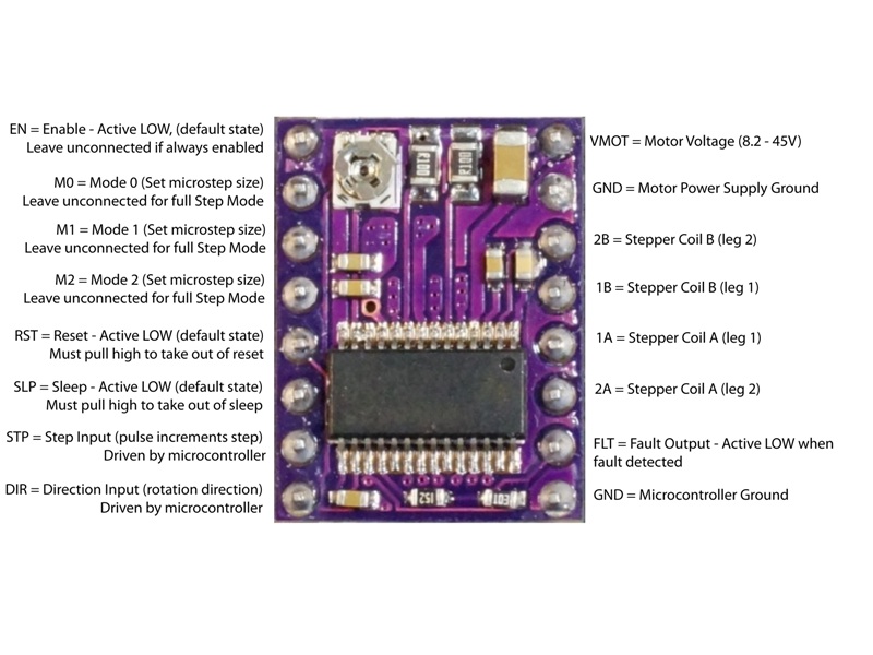
I know this is a stupid question but are you sure your motor is connected to the DRV8825 that uses pins 5 and 2?
Another thought, have you got the motor wires connected correctly. Use your multimeter to identify which pairs of wires belong to each coil. Then the wires for one coil should go to A1 and A2 and the other coil to B1 and B2
I believe you are correct that Pin 8 activates all the enable pins. I presume you have tried HIGH as well as LOW
From the diagrams, it should be pin 5 and 2, unless there is a different diagram somewhere, but just in case, I just tried:
Slot X: Pin 5 and 2, then pin 6 and 3 then pin 7 and 4 (2 times each setting pin 8 LOW and HIGH)
Then moved on to slot Y and Z and repeated the same test (Those pin pairs are all the pairs for the different axis).
I also checked the wires from the motor, it matches correctly, each coil wires are next to each other and go to 1A/2A and 1B/2B
it seems everywhere I look, I always find the same pin for the different axis like this one:
I don't know if it says much, but I ran my multimeter in series with the power supply and it showed no change during the run of the sketch 0.01A except when I would press the reset on shield to restart the sketch then it would drop to zero.
Anymore things I can test by chance ?
Thank you again for your help.
PS: I also tested with another arduino brand board, which I know works also. I don't have another shield other than the one on my Mega on my 3d printer and don't really want to mess with my printer right now.
At this point, I am thinking the cnc shied if defective, so are the other 3 drivers. I don't believe I did anything wrong to it, went step by step making sure everything was right. As I said, I had to re-bend a LOT of the pins (maybe a customer return they tried to resell), including the pin blocks the stepper drivers plug into (no back and forth, just careful bending as I've done before on pc CPUs).
Coersum:
I also checked the wires from the motor, it matches correctly, each coil wires are next to each other and go to 1A/2A and 1B/2B
That does not actually tell me that you checked the wires with your multimeter.
I can't think of anything else. I have a RAMPS shield but not a CNC shield.
Can you connect up one of the drivers with the Arduino and the power supply without using the shield?
Can you take the DRV8825 out of the shield and check that the step and direction pins show HIGH and LOW when you use a simple digitalWrite( ) for the relevant pin. Also check the connection from the DRV8825 socket to the motor connections.
Yes that's what I meant by checked (with multimeter), found that the coils were connected correctly.
I connected one of the driver with my breadboard but had the same problem, voltage is good, but not getting HIGH LOWs when doing a digitalwrite, motor still not turning.
I checked with different motors again just to be sure and retested my motors by hand. At this point I contacted the company for a return, I am getting a replacement on sunday.
Thank you for all your help.
PS: also sry for late reply, been busy with kids hockey this weekend.
If you bought the stepper cables from an online source then double check the colours match end to end.
Had a few here where sloppy workmanship had wires crossed over at the terminating ends.
Different driver boards may also have different orientation in the shield and is something to be careful of.
if one driver works with one motor then disconnect the power and move them to another location eg. X to Y etc.
That will confirm the shield is at fault or not.
Once you have confirmed the shield is OK then proceed to swap out ONLY a driver but take care to set up the voltages for the drive current to match what you had on the working driver.
Be careful of heatsinks shorting out pins if you have them as they can drift easily if they use the sticky tape to hold them.
My preference there is to clean off the sticky tape from both surfaces and use a dab of superglue.
@ballscrewbob
I bought everything as a kit (steppers, cables, drivers) and made sure to check the Enable pin for positioning.
Turns out none of the drivers work, I know that because once I got my new drivers/shield, I plugged everything in like the last one and everything worked straight away (crazy right ?)
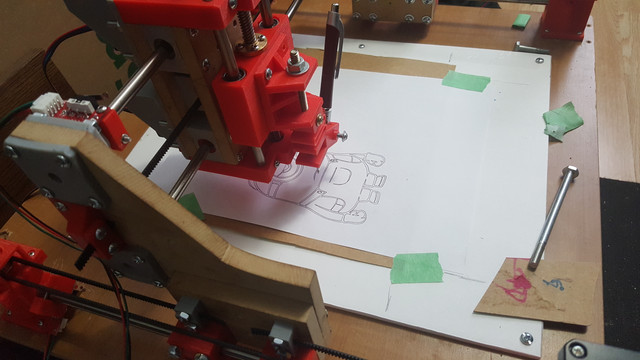
My cnc is plotting just great right now till I figure spindle details.
Be very wary of spindles.
They add a lot of vibration (some unseen or heard) and can cause 3d parts to fail or wear quickly.
Also be very careful choosing a spindle.
Better to pay extra and have one with an ER11 collet that helps reduce vibration a bit.
Went through 3 of the cheaper ones before I caught on how bad they are and bit the bullet to go bigger.
Never regretted the move.
PS if you have a 3d printer jump to near the end of the thread I linked as Danger is currently making a spindle mount for his machine with a 3d printer to suit the better spindles. Am sure he would share his findings with you.
