Wrong analogread values when using CD74HC4067 multiplexer on Arduino Uno

I am reading analog values through my CD74HC4067 multiplexer, using an Arduino Uno with the following setup. I use 8 channels on my multiplexer to read values from high impedance analog FSR pressure sensors.

The Arduino code is provided below:

//Mux control pins
int s0 = 2;
int s1 = 3;
int s2 = 4;

//Mux in “SIG” pin
int SIG_pin = A0;

void setup(){
pinMode(s0, OUTPUT);
pinMode(s1, OUTPUT);
pinMode(s2, OUTPUT);

digitalWrite(s0, LOW);
digitalWrite(s1, LOW);
digitalWrite(s2, LOW);

pinMode(SIG_pin, INPUT_PULLUP);

Serial.begin(9600);
}

void loop(){
  for(int i = 0; i < 8; i ++){ 
    Serial.print("Value at channel "); 
    Serial.print(i); Serial.print("is : "); 
    Serial.println(re
    adMux(i)); 
    delay(500); 
  } 
} 

int readMux(int channel){ 
  int controlPin[] = {s0, s1, s2}; 
  int muxChannel[8][4]={ {0,0,0,0}, 
  {1,0,0,0}, 
  {0,1,0,0}, 
  {1,1,0,0}, 
  {0,0,1,0}, 
  {1,0,1,0}, 
  {0,1,1,0}, 
  {1,1,1,0} }; 
  //loop through the 4 sig 
  for(int i = 0; i < 3; i ++){ 
    digitalWrite(controlPin[i], muxChannel[channel][i]); 
    } 
    //read the value at the SIG pin 
    int val = analogRead(SIG_pin); //return the value 
    return val; 
  }

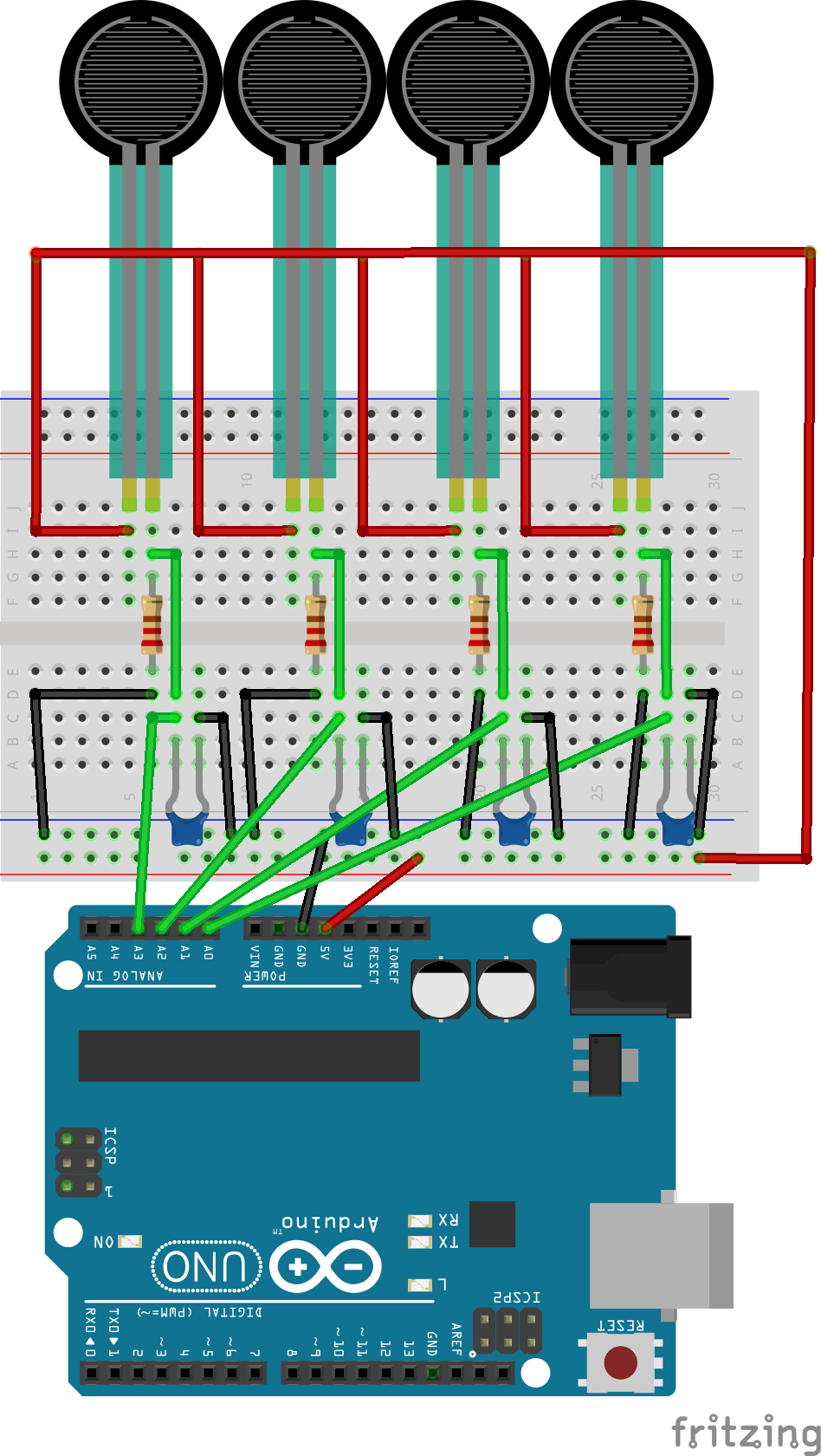
The problem I am having is that I am reading floating values in my serial monitor, which don't significantly change when pressing any of the sensors. I have tried them directly on the Arduino with bypassing the multiplexer, where they values are printed correctly (see circuit diagram below). There is probably something I am misconnecting in my multiplexer circuit or the corresponding code. Please help me out. Thanks in advance.

Connect S3 to gnd. Not floating.

The below quote comes from section 24.6.1 Analog Input Circuitry of the ATMega328/P datasheet. You might want to think about how it applies to the problems you've encountered.

The ADC is optimized for analog signals with an output impedance of approximately 10 kΩ or less. If such a source is used, the sampling time will be negligible. If a source with higher impedance is used, the sampling time will depend on how long time the source needs to charge the S/H capacitor, with can vary widely. The user is recommended to only use low impedance sources with slowly varying signals, since this minimizes the required charge transfer to the S/H capacitor.

You appear to have the FSRs just connected to 5V, so, if you get your code right they will just read as 5V as changing their resistance won't alter the voltage, because there will be negligible current flowing through them. You need a 'bottom' resistor between the ADC input and ground. I can't tell you the value, what is the resistance of an unloaded FSR and how much does it vary when you apply pressure?

Does the error only occur in the simulator or in the real assembly?

I included your suggestion (also shown in the updated circuit diagram in the original post), but no success however.

@PerryBebbington, I did use an additional resistor to create a voltage divider (I just didn't include it in my circuit diagram). I've updated the diagram in the original post. Everything is working as expected, except for the crosstalk among the input pins. When not using the multiplexer, I could shunt my analog input pins with 100nF capacitors each (as seen in my diagram above). However, when I connect my 8 channels on the multiplexer to separate capacitors to ground or the common signal terminal to ground with a capacitor, I still experience crosstalk among the pins. How can I fix this?

Try taking 2 readings from each input, discard the first, use the second.

Hi, @jellevandereerden

Please do not update previous posts, it confuses the direction of the thread for anyone wanting to use this to solve a problem of their own.

Post updates in new posts please.

Do you have a DMM? Digital MultiMeter?

Thanks.. Tom.. :smiley: :+1: :coffee: :australia:

Already tried that, but didn't solve the problem.

Sorry I don't have any other suggestions, hopefully someone else will. If I think of anything else I will mention it.

1 Like

Hi,
Instead of relying on the one resistor to gnd when using the 4067.

Place a resistor on each of the inputs of the 4067, so each sensor has its own potential divider resistor instead.

Tom.. :smiley: :+1: :coffee: :australia:

I assume this is a copy/paste error.

Try this sketch, with the FSRs connected between inputs and GROUND. No resistors.
Leo..

// 8 FSR between mux inputs and ground
const byte controlPin[] {2, 3, 4};
const byte muxCommon = A0;
int FSRvalue[8]; // 0-7

void setup() {
  Serial.begin(9600);
  pinMode(muxCommon, INPUT_PULLUP);
  for (byte i = 0; i < 3; i++) pinMode(controlPin[i], OUTPUT);
}

void loop() {
  for (byte i = 0; i < 8; i++) { // 8 channels
    for (byte s = 0; s < 3; s++) digitalWrite (controlPin[s], bitRead(i, s));
    FSRvalue[i] = analogRead(muxCommon); // dummy read
    FSRvalue[i] = analogRead(muxCommon);
    Serial.print(FSRvalue[i]);
    Serial.print(", ");
  }
  Serial.println("");
  delay(250);
}

This topic was automatically closed 180 days after the last reply. New replies are no longer allowed.