"xor" power source circuit?

I have a device that pulls power from a usb cable. This works most of the time.
After talking with the designer, I can increase the range it works if I use an external power supply.
I can cut the trace for power & solder in a wire for the external power source.

This works great... BUT

I wold like to automatically select the external source if it exists, otherwise use the usb power.
I had thought about using a couple diodes, but this wouldn't 'cut-off' the draw from the usb.

Is there a way to do this w/o a relay, which would be easy...

Hi
If you look at the schematic of any arduino board you will find that circuit already implemented there near the DC jack .
Have you ever wonder what will happen if you power the board using the DC jack and at the same time power it by USB?
The board only accepts power from one power source at a time,thanks to a mosfet transistor in the board that cuts or turn on based on the power source.
You could use the same circuit for what you want or extract the main idea.
Happy coding

The standard solution here is just a diode in series with the power, like you mentioned.

Why must any current draw from the USB be prevented when the external supply is connected?

If that's a requirement, use a MOSFET to switch the power. But I don't think it actually is a requirement, I think you just think it is.

It's not an XOR if one of the inputs has a priority. XOR means just that. EITHER OR BUT NOT BOTH.
It doesn't mean A if A exists otherwise B.

The simplest solution is connect a relay coil to the external power supply input connector so when you plug in the external supply, the relay coil is energized. Connect the LOAD to the COM and the usb to the Normally Closed (N.C). Connect the External power supply to the N.O. contact. When the coil is DE-energized (OFF) , load will be connected to the USB power. As SOON as you connect the external power, the relay will be energized and the external power will be connected to the load at the same time the USB is DIS connected from the load.

Thanks for the feedback -- I'll look on an arduino to figure out which mosfet they use, I really wanted to avoid mechanical / coils.

According to the board developer, it's required I disconnect the usb power, not just supplement it.
It's an oscilloscope tool, (or a tool for an oscilloscope).

I didn't look at mosfets because I thought they connected when 'active', not disconnect when active...

Thanks!

(PS: @drazzy -- A friend built one of your 841 boards and sent it to me.. very cool, I love the two hardware uarts & 3 timers!)

daveyjones:
I didn't look at mosfets because I thought they connected when 'active', not disconnect when active...

That depends completely on how you use them.

I have a device that pulls power from a usb cable. This works most of the time.
After talking with the designer, I can increase the range it works if I use an external power supply.
I can cut the trace for power & solder in a wire for the external power source.

This works great... BUT

I wold like to automatically select the external source if it exists, otherwise use the usb power.
I had thought about using a couple diodes, but this wouldn't 'cut-off' the draw from the usb.

Is there a way to do this w/o a relay, which would be easy...

There may be a simple way to do it.

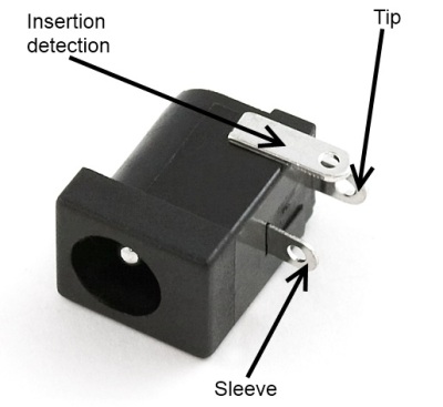
The key factor to make this work is certain kind of charging jack
(I think it is the opposite of this one)

that disconnects the load when the charger is plugged in. The USB would be connected to the "load" pin and the "device" is connected to the "battery" pin. The External P.S. substitutes for the "charger". When the "charger" is NOT connected, the "load" is CONNECTED to the "battery". When the "charger" is PLUGGED in, it separates the "load" (USB) , from the "battery" ("the device"). The "charger" (external P.S.) is now CONNECTED to the "battery" (the "device").
Understand ?
(please don't ask me where to find that connector). Everyone is familiar with them but very few people actually know where to find one. I can only think of one person who probably knows: Crossroads.

"Active" ? Active what ? (LOW, HIGH ?)

If you are going to talk about MOSFETs , you MUST FIRST understand the meaning of "Gate-Source Voltage" . ( Vgs) In order to do that you must FIRST understand the difference between N- channel mosfet and P- channel mosfet. In order to do that hou must FIRST understand that N- channel fets have a positively biased Drain, with respect to source. Typically the Source is connected to GND and the Drain SINKS the LOAD current , so the Gate- Source voltage is positive, with respect to the Source. If thd Load Vcc is +12 V , for example, the Gate-Source Voltage will be +12 V. A P- channel , on the other hand , will hace a negatively biased Drain ,with respect to Source, so the Source will be connected to +12V and the Gate-Source voltage will be negative , with respect to Vcc. If Vcc is +12V, the Source is connected DIRECTLY to +12V and the Drain SOURCES ( NOT SINKS) the current.
If you don't know the difference between SOURCING and SINKING, well then you are not ready to talk about MOSFETS, period. If you do , then the Gate-Source voltage for a P-channel with a +12V Source is -12V , (Gate to Source) . An arduino cannot supply +12V to turn on an N- channel mosfet. It can supply 0V to turn on a P- channel mosfet. It CAN supply 0 V to turn OFF an N-channel but it cannot supply +12V to turn OFF a P-channel. Do you see the relationship between GND , Vcc, Gate , and Source ? . If it's an N-channel, the Source is grounded, and the Gate needs to supply the Vcc voltage to turn it on and 0V to turn it off. If it is a P-channel, the Source is connected to Vcc and the gate needs to supply 0V (or less) to turn it on and +Vcc to turn it off.

N-channel P-channel
(Vcc = +12V) ON +12V 0 to -12V
OFF 0V to -12V +12V

So that's where mosfet gate drivers come in. They can accept 0 to +5V and output +/-12V ( assuminv , of cource you supply +/-12V to their +Vcc/-Vee pins. In short, if are using N-channel , you are in the current SINKING business. If you are using P-channel, you are in the current SOURCING business. And if you do NOT have mosfet drivers , you are OUT OF BUSINESS.

UNLESS, you are using a Logic Level N-channel , like the FQP30N06 ( Supplier: SPARKFUN)
An arduino can turn ON/OFF one of these with a 0V/ 5V logic signal on the gate, without any gate driver. They have Logic Level P -channels but 5V is not enough to turn them OFF with the source connected to +12V. If you stick with the logic level N-channel you don't need a gate driver.

THIS is the gate driver I use (Vcc = +12V) It comes in different flavors depending on your logic requirements.

If your Vcc is +12 to +15v , this should work for you.
It can supply 0V /+12V to turn ON/OFF P-channel mosfets and +12V/0V to turn ON/OFF N-channel mosfets.

Note: Mosfet Gate drivers are ALSO used to boost gate current for driving high power devices. Nothing I have said relate to this. I only mention them for their LEVEL-SHIFTING applications.

when I say "active" I mean not floating.

ie: When "external power" is not applied, that line is floating, it's not connected to anything; I want the usb power to be connected. When an external power is connected, I want the usb power to be disconnected.

The N channel & P channel mosfets I have on hand do not "connect" until either they are driven to ground or V+.

It seems I need just the opposite, something that is connected while floating, and disconnects when driven high (external volt applied) to disconnect the usb...

I'll read more on gate drivers...

Why don't you look at how it is done on the UNO

I don't see why that wouldn't work for your application. It is exactly what you are describing.

Uno checks that Vin/2 is greater than 3.3V, if so Vin source is used for power.
That circuit could be adapted for lower voltage, so if external 5V was being applied it could cut out the USB power.

Change RN1A to 5k and RN1B to 7k for a voltage divider that outputs 5V for a 12V input.

12V * [5k/(7k+5k)] = 5V

VOLTAGE DIVIDER

Have to pull the 4-resistor pack RN1 off the board to do that.
I don't recall, are RN1C and RN1D used for anything?

The OP isn't using an arrduino. He has to duplicate that circuit. He's designing a "DEVICE",and needs the same function we are discussing about on the arduino. He wants to add that function to the "device" he is designing. There is no arduino in this post (to my knowledge).

Right -- the 'device' feeds an oscilloscope & reads info from an arduino (or any circuit, I am using it with arduino). Sorry I didn't make that clear. In order to use it at higher miliamps, I need to not use the usb power, but my own higher (amperage wise) power supply.

Technically, we cannot actually answer your question if you don't tell us the voltage of the external power supply.
Assuming that it is +12V ...

Do you NOT realize that we have just told you EXACTLY what you need to do ?
Did you somehow miss that ?

5v -- all 5v; just able to supply higher amperage than usb ...

In that case use the UNO circuit as is, with no changes.

Use 6.8k for RN1A and 3.3k for RN1B.

5v*6.8K/(6.8K+3.3K)=0.673 *5V = 3.366V.

Do you understand ? (EXACTLY what you need to do ?)

We have had no confirmation that you understand anything we have said (about the solution), (with the exception of the question you just answered)

Please confirm .

I have an understanding. Thank you. I will look at uno schematics for chip specs & circuit design.

"will look" ?
That soundd like FUTURE tense. So you haven't looked at it yet even though I gave you the link ?
How long does it take ? ( 15 seconds ?)

Really ? What circuit design do you think we are talking about ?
WHAT chip specs ?
Who said anything about chip specs ?
Did I mention chip specs ?
What EXACTLY do you think we are talking about ?

C'mon raschemmel, tone down the attitude. Give the OP a chance to look at Uno schematic, the FET used for power switching, its current capacity, and then reply.