Hello to all LCD Pro's (and other nice people :D)
I'm new to this board an relative new to arduino. Until now, i found pretty much everything i had a question to in this forum or the web. But now, i found an YL24064-13 (equal to -27) Display. All i found is this page: http://andilcd.de/44.html?&no_cache=1&L=1&pid=61 and this datasheet http://andilcd.de/medien//de/download/stdgraph/andilcd_stdgraf_draw_de_yl_R_24064-27.pdf .
So, i'd be very happy if someone could tell me, how i should do the wireing to an DUE and if possible show me an library/example for such a display (graphic 240 x 64).
Thanks in advance for all answers  !
!
Hi
This is a T6963 display as mentioned in the datasheet. u8glib might work.
Oliver
Thanks Oliver for your quick reply.
Your idea with T6963 seems really wright. I connected the LCD like described on the page and loaded/modified the lib as described, but i don't get it working. Also, i don't have a "reset" bin in the datasheet like in description...
But thanks for your work!
Hope for more information.
Greetz
reset = pin 10
The display might require -10 V (not clear from the datasheet)
How did you connect pin 4?
Oliver
I'll try the -10V today. I tried Pin 4 with +5V...  wrong? ^^
Have a look here: http://www.newhavendisplay.com/specs/NHD-24064CZ-FSW-GBW.pdf
Your vee pin: I think is an output (although marked as input on your datasheet, but i found newhaven displays description more trustable). You can do this: Apply 5V to your display and measure voltage at your vee pin. If it is -10 V you do not need to apply extra -10V, because it is produced on board. You can then use the vee pin as source for pin 4. However you need a resistor devider or adjustable resistor to obtain the voltage for pin 4.
Pin 4 is used to adjust contrast and must receive a voltage between -5 and -10V (see the newhaven doc).
If there is no voltage on vee, then you need an external -10 source to get the voltage for pin 4 (v0)
Oliver
Hello!
So, i tried different things. I have a voltage on the Vee pin, but i also created a -10V power source.
Item, i found a legit wiring and librarie, fitting for my lcd https://code.google.com/p/arduino-t6963c/wiki/T6963c .
I connected everything, as mentoined. I also bought a UNO today, just in case (using right now).
After a change in the .h and .cpp from #include "WProgram.h" to #include "Arduino.h" i also don't get any errors any more while compiling.
So far so good, but the display won't work.... It's not showing anything.
I tried prretty much everything now, nothing helped. Any ideas?
Greetz Alex
Yes, you will need the Uno board, because your display requires 5V TTL logic.
I have tested u8glib sucessfully with the T6963 display.
Oliver
Hello
So, i re-built the whole circuit u8glib-like. I think the wiring should be wright, only question i have, wich pins are the cs and a0 on the display? cs=ce and a0=c/d or something? I allready switched them...
For LCD Pin 4 (LCD Voltage) a 10k poti (-10V/Pin 4/GND) is wright?
I loaded several sketches, but the screen remains blank.
I don't know what else i could do.... =(
Hi
Yes, a0 = c/d
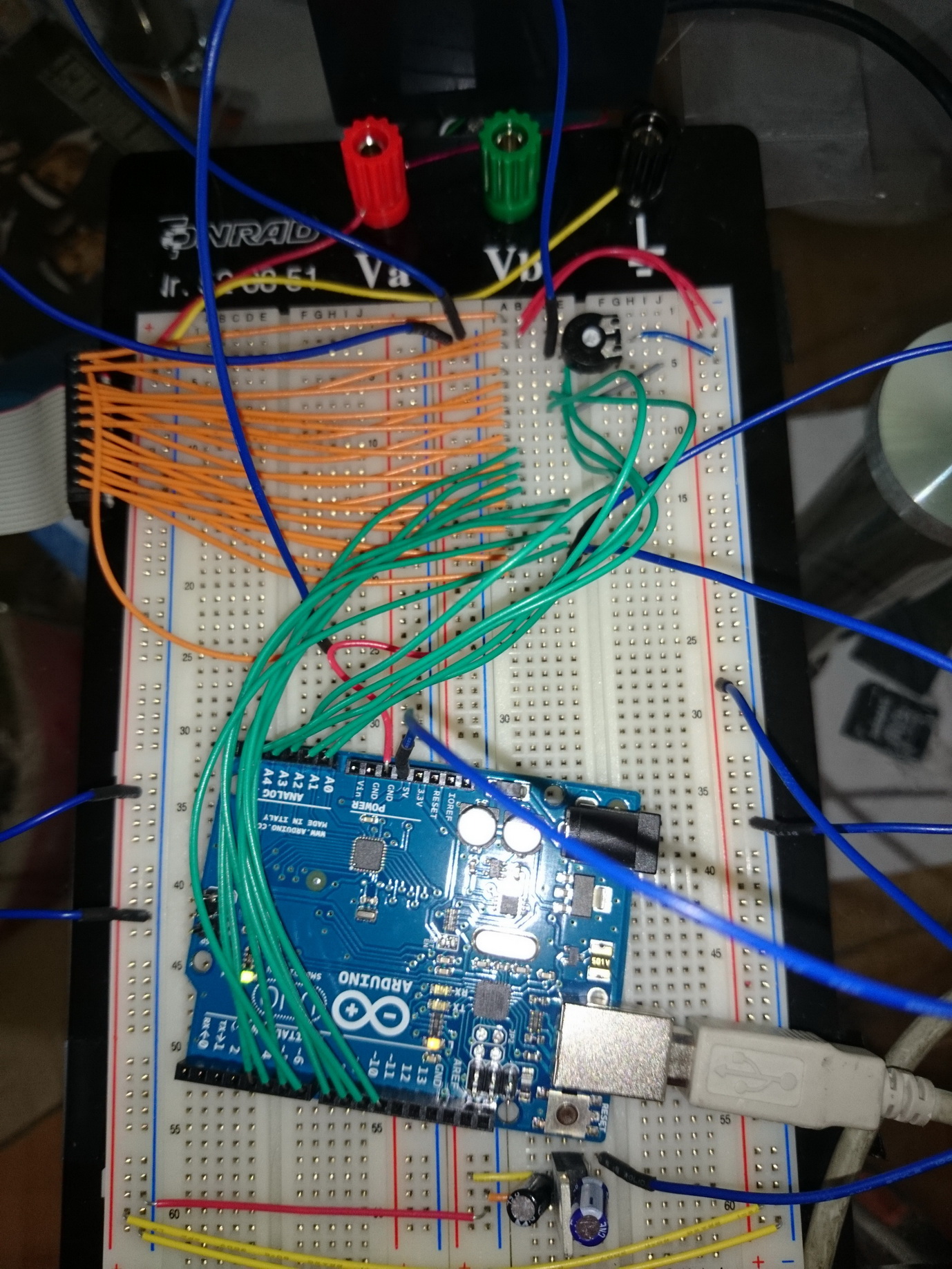
Maybe you can most a picture of your setup and the constructor call, you use.
Also note, that often more than -10V are required.
Oliver
Hello
Attatched, the images. I don't think you'll see much... 
As you can see, for the -10V i use an Battery, so i have a 12V source.
Constructor call:
U8GLIB_T6963_240X64 u8g(8, 9, 10, 11, 4, 5, 6, 7, 14, 15, 17, 18, 16); // 8Bit Com: D0..D7: 8,9,10,11,4,5,6,7, cs=14, a0=15, wr=17, rd=18, reset=16
thanks...
Maybe i missed this, but how did you actually add your -12 V?
- of the battery must be connected to GND
- to the one and of the variable pot.
I have not really seen this on your picture.
Oliver
Hi
I generate a -12V tension with an lm7912 (Picture 4). But i'll try it like you described.
Good night!
Edit: I found my fault... I'm actually the dumbest person alive...  Such a big hand, it needs for a facepalm for this stupidity doesn't exists... I really thought, i could connect the lm7912 to +12V and GND and it generates - 12V... That hurts I'll do it with +12V as GND when i'm at home...
Thanks for not laughing to hard... xD