So length of your square signal is one half cycle? In that case CHANGE is ok.
Why you put attachInterrupt in loop??
You probably have some hardware issue right now but I would estimate that after you might have problem with your interrupt. In your code you have a delay of 750us for firing, but when you want to dim more that delay would be several milliseconds. Not ideal inside an interrupt.
Try this code
volatile int triacpulse = 3;
volatile int dimming = 128;
void setup()
{
  // put your setup code here, to run once:
  pinMode(triacpulse, OUTPUT);
}

void loop()
{

  dimming = 75 * 10;
  attachInterrupt(digitalPinToInterrupt(2), acon, RISING);

}
void acon()
{
  delayMicroseconds(dimming);
  digitalWrite(triacpulse, HIGH);
  delayMicroseconds(50);
  digitalWrite(triacpulse, LOW);
}I'm not sure whether you can use delayMicroseconds() in an interrupt.
I know that you can't use delay(). See attach interrupts() for more details.
You can, but short as possible
Thanks for that clarification, kmin
I mean, that 10-20us delay to trigger triac is ok, but the dimming delay 0-10ms is not.
Could be done with separate timer interrupt.
no it doesnt , the zero detector is working but the signal is still not coming out of pin 3 . do you perhaps have any tutorial on how to make it from scratch ? and thank you for your help .
move that attachInterrup from loop to setup and set dimming=0 and have a look if you get output
I just ran that code on an uno and it worked, so I suspect you are doing something wrong in the proteus simulator.
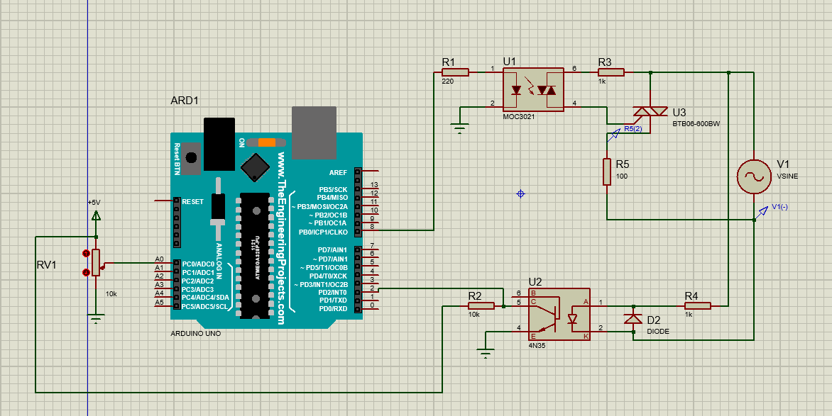
Hello , i am woking on an AC dimmer project , on isis proteus evertything is wroking but in practical only the zero cross signal is there , the arduino doesnt deliver the triac pulse .
note : im using an oscilloscope to visualize the signals .
here is the schematic and code i'm using :
#define scr_trig   8
#define pot       A0

bool ZC = 0;
uint16_t alpha;
void setup(void) {
  Serial.begin(9600);
  pinMode(scr_trig, OUTPUT);
  digitalWrite(scr_trig, LOW);
  attachInterrupt(0, ZC_detect, CHANGE);       // Enable external interrupt (INT0)
}

void ZC_detect() {
  ZC = 1;
}
void loop() {
  if(ZC){
    delayMicroseconds(alpha);
    digitalWrite(scr_trig, HIGH);
    delay(1);
    digitalWrite(scr_trig, LOW);
    ZC = 0;
    alpha = analogRead(pot) * 10;
    if(alpha > 10000)
      alpha = 10000;
  Serial.println(alpha);

  }
}
is there is any trick that can be done
any help would be great.
best regards,
I'd make the pulse a bit longer and output alpha only if changed.
Why don't you try the code I gave you here
https://forum.arduino.cc/t/ac-dimmer-dimming-pulse-not-coming/1260230?u=jim-p
hello , i am working on an AC dimmer project , the zero cross detector is workin and delivering a square signal but the arduino doesnt read it . i used a code to count the change in the interrupt pin but it kept showing a zero . here is the code i used :
#define triacpulse 8
int dimming = 128;
volatile int count = 0;
void setup() {
  // put your setup code here, to run once:
    Serial.begin(9600);
pinMode(A0,INPUT);
pinMode(triacpulse, OUTPUT);
  pinMode(2, INPUT_PULLUP);

}
void incrementCount() {
  count++; // Increment the count whenever there is a change on pin 2
}
void loop() {
int  sensorValue=analogRead(A0);
  dimming=75*sensorValue;
  attachInterrupt(digitalPinToInterrupt(2),acon,CHANGE);
  attachInterrupt(digitalPinToInterrupt(2), incrementCount, CHANGE);
  Serial.println(count);
  delay(1000);
}
void acon(){

delayMicroseconds(dimming);
digitalWrite(triacpulse,HIGH);
delayMicroseconds(10);
digitalWrite(triacpulse,LOW);


}
the thing i need help with right now is how to read the signal from the zero cross because without it the triac pulse wont come .
any help would be great.
best regards,
I already gave you a complete sketch (event two) in your older thread.
As far I see, it is your 4rd topic about the issue. Opening a duplicate threads is a violation of the forum rules.
1 Like
Did you try the code I gave you in this thread?
https://forum.arduino.cc/t/ac-dimmer-dimming-pulse-not-coming/1260230?u=jim-p
@ashisalluneed, stop cross-posting. Threads merged.
What a mess here.... ![]()
If you are not willing to read advices and consistently follow , answer and update , may I suggest you a ready made module with library included:
Using your code from post #31, I'm getting the triac trigger pulses.
You need to rethink what the maximum value of delayMicroseconds(alpha); can be.
Watch what happens when alpha >= 9000.
Tested on an Arduino Uno, using a function generator to provide 50Hz zero crossing signal, and simulated potentiometer sweep.
The oscilloscope trace shows:
- Channel 1 - 50Hz Zero Crossing Signal.
- Channel 2 - Triac Trigger Pulse.
- Channel 3 - Simulated Potentiometer Sweep.
- Channel 4 - Serial Output.

1 Like
In your code in post # 34, you have got the following two lines in loop()
attachInterrupt(digitalPinToInterrupt(2),acon,CHANGE);
attachInterrupt(digitalPinToInterrupt(2), incrementCount, CHANGE);
kmin has already told you that the attachInterrupt() should be in setup(), rather than in loop().
You can only have one interrupt service routine on pin 2.
When you try and use attachInterrupt() for the second time, it just overwrites the first instance.
This means that the ISR 'acon()' never gets called. Hence no triac trigger pulses.
(statistically, it could if the interrupt happens to arrive when the code has executed the first line, but not the second. That is unlikely to occur.)
The ISR 'incrementCount()' gets used instead.
Because you only print the value of the counter every 1000ms, it will have been incremented 100 times between each print.
1 Like