I am a beginner and this is my first post. To avoid duplicating a previous topic, I will make reference to it below:
I'm running a simple test program just to try and turn the motor for the first time. I've copied it from this Makerguides tutorial.
/* Example sketch to control a stepper motor with Arduino Motor Shield Rev3, Arduino UNO and Stepper.h library. More info: https://www.makerguides.com */

// Include the Stepper library:
#include <Stepper.h>

// Define number of steps per revolution:
const int stepsPerRevolution = 200;

// Give the motor control pins names:
#define pwmA 3
#define pwmB 11
#define brakeA 9
#define brakeB 8
#define dirA 12
#define dirB 13

// Initialize the stepper library on the motor shield:
Stepper myStepper = Stepper(stepsPerRevolution, dirA, dirB);

void setup() {
  // Set the PWM and brake pins so that the direction pins can be used to control the motor:
  pinMode(pwmA, OUTPUT);
  pinMode(pwmB, OUTPUT);
  pinMode(brakeA, OUTPUT);
  pinMode(brakeB, OUTPUT);

  digitalWrite(pwmA, HIGH);
  digitalWrite(pwmB, HIGH);
  digitalWrite(brakeA, LOW);
  digitalWrite(brakeB, LOW);

  // Set the motor speed (RPMs):
  myStepper.setSpeed(60);
}


void loop() {
  // Step one revolution in one direction:
  myStepper.step(200);

  delay(2000);

  //Step on revolution in the other direction:
  myStepper.step(-200);

  delay(2000);
}
My issue is exactly the same (motor turns normally then starts shaking) only that I am using a 12V stepper motor with the following specs:
If I remove the extra power supply and let the VIN pin connected to the Uno, it all runs fine but it's very weak. With the VIN pin disconnected and external 9V supply, the motor runs normally for a short while then it starts shaking and the motorshield seems to overheat.
Could you please help me identify what is wrong, perhaps the driver board is inappropriate for the stepper motor I am using. Thanks in advance for any recommendation or advice.
Please, describe "the same" symptoms you are having on this thread, and include a schematic or interconnect drawing with your sketch. It will help others help you.
Did you attempt any of the five suggestions from the first link, or the fifteen suggestions from the first link in the first link, or any of the twenty-five suggestions in the second link of the first link?
The result was this:
"...Thank a lot to have written those both wonderful posts ! It explains very well and easily!
Thanks also to have answered yesterday to my posts !"
Generally we would not recommend that driver board for NEMA 17 or greater.
L298, L293 ULN2003 drivers are notorious for consuming excess power and being inefficient for all but the most basic and small motors.
When it comes to stepper motors there are lots of newer and much more efficient drivers available.
A4988, DRV8825 or the TMC series allow much better control.
Even the larger drivers such as the Tb6600 etc.
In most cases at least 12 volts is needed for NEMA 17 or above.
Power supply should also have a good amperage (3 Amps or better).
That is expected with a typical low impedance stepper, for which the L298 is not designed.
Check whether you do in fact have the high impedance motor described in the motor data sheet you posted. Measure the winding resistance, which according to the data sheet is 34 Ohms.
Thank you very much for this! I just checked the motor and it seems it's 1.5 Ohms per winding which explains the behaviour. Looking at the website where I purchased it, it seems that I received an identically sized motor (42x34mm), rated 2.25V, 1.5 Ohms and 1.5A... I will get it replaced and hopefully it will work like in the tutorial.
thank you for the recommendations. I will reconsider my choice of stepper motor and driver board now that I read more about them. My application is a rotating pole on a boat powered preferably directly from the 12V battery (13.5V when full).
How big is the pole ?
What will it weigh ?
Will it have anything else on the pole that may affect the torque eg a pulley ?
Will there be a wind load to take into account ?
Those are just part of a total equation you will need to consider.
The NEMA 17 might do what you need but the driver certainly needs careful consideration.
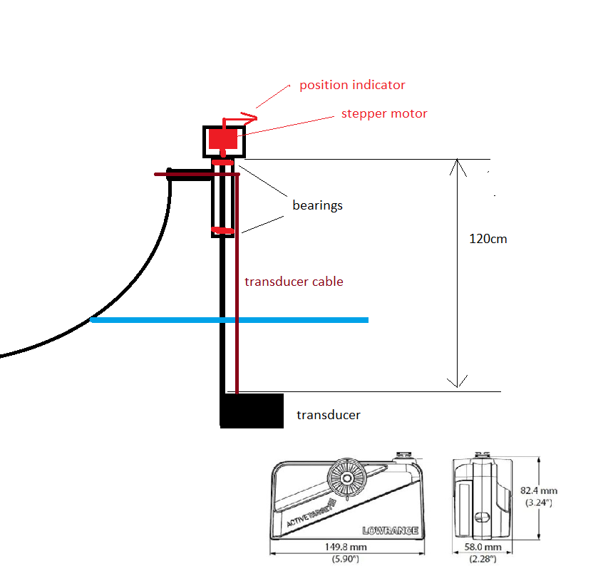
The motor will move a 1.2m x 10mm stainless-steel shaft inside the pole, which will be mounted at the side of the boat, and will go about 40cm in the water. At the submerged end, there will be a transducer like the one below:
I presume a 2kg/cm motor will work when the boat is stationary but as soon as I'd start moving the boat, it will be overloaded. The pole would be in the water for boat speeds of up to 10km/h. For the moving boat scenario It would need to be much more powerful so the ideal specs would be:
high torque
a speed of up to 20-30rpm would be sufficient
12V or 24V (I have 2 separate batteries and I can power it from either one)
preferably with a double shaft so I can use the secondary one to indicate the rotation angle
Further reading pointed in the direction of a geared NEMA 17 such as this one.
Would it be suitable and would it work with the driver boards above?
If you are using all the 25 foot below water than you will almost certainly require a much larger stepper when traveling. Either a NEMA 34 or larger. And almost certainly a much better driver capable of running such a large stepper capable of at least 3.5 amp or more. The 24 volt supply will almost certainly be needed too.
Consider also allowing the project to disable the stepper when drag becomes too much so allowing to to become more like a free rudder if you are moving at speed.
OOPs missed the 40 CM bit bit that is still a lot of drag at speed.
Yep I noticed but as a mech eng. I would still like to see a larger motor from the get go.
Belt and braces type of guy here and make my things to last
Also bear in mind you probably want to do one of two things with the cable.
A. Limit its rotation to 350 degrees to prevent tangling inside the tube and eventual breakage.
B. Use a slip ring connection at the top to allow it to rotate as much as you want.
But clearly the slip ring would have to be a slightly more waterproof version.
EDIT...The lower bearing would also have to be a double sealed waterproof type unit. suitable for the type of water you are working in. Saltwater will require a different bearing from freshwater in some cases because of corrosion factors.
thanks for the suggestion. I'll go with NEMA 34. The pole would be in the water for speeds up to 6mph, the maximum speed of the electric engine.
Thanks for the tip on the rotation too. Version A would be sufficient. I was hoping to be able to limit the rotation from the code with respect to an initial angle of the stepper.
The bearings I have now are non-saltwater indeed and I haven't thought of a way to seal the motor and the gaps between the shaft and the outer pipe. I will look into rubber seals for every possible way in. Generally it would be used it in freshwater but every once in a while it could see some saltwater too.
As full travel is not needed something close to this is all that would be required and the outer shaft could include a simple stop mounted on the NEMA shaft to prevent excess travel.
Great idea with the cable gland and the flange. I found some already threaded stainless steel pipe that could work. The physical implementation seems more challenging than the script itself so far.
The transducer works almost like a video camera so it would rotate left/right to scan for (moving) targets The speed of rotation of about 20-30rpm would be sufficient so, if possible, I would trade off some speed for extra torque. Would a geared motor not work in this case?
It is possible that a geared stepper would work for the sort of speeds you are looking at.
Even cheaper and simpler would simple be a DC motor on a crank, something like an old wiper motor.
Speed control on a DC motor is so much easier to manage and no stops would be needed.
The application is slightly more complex. The transducer would have several functions triggered by an IR or bluetooth remote:
scan - it would automatically move left/right
manual left/right, up/down to change speed
stop and target lock where it would remain locked on the target. The angle adjustment would be derived from the change in boat position and rotation. I intend to use a gps and a gyroscope for this to track the boat movement. As for the motor, it would need to be adjustable in small steps.
Would the A4988 driver work with the geared stepper motor such as the one below:
Specs are 1.7A at 12V, 30kg/cm, 20rpm, which should hopefully be sufficient.