16x2 LCD display problem

problems with 16X2 LCD:
2

3

Hardware used:
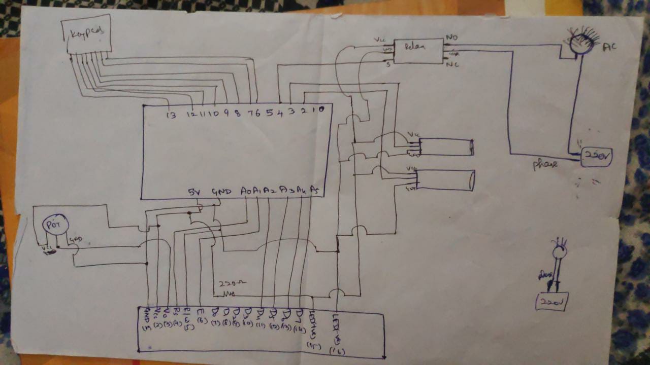
arduino uno, two 5v 10A relay,16x2 lcd display without i2c, 4x4 keypad, two Proximity IR sensors(yellow color), 5v ac-dc adapter,

kit components:
We have used a box in which there is dot matrix board on which arduino uno and relays were installed using screws and glue sticks with all the wires like gnd and vcc are soldered backside..

outside the box we have lcd
components away from kit without physical contact sensors , keypad

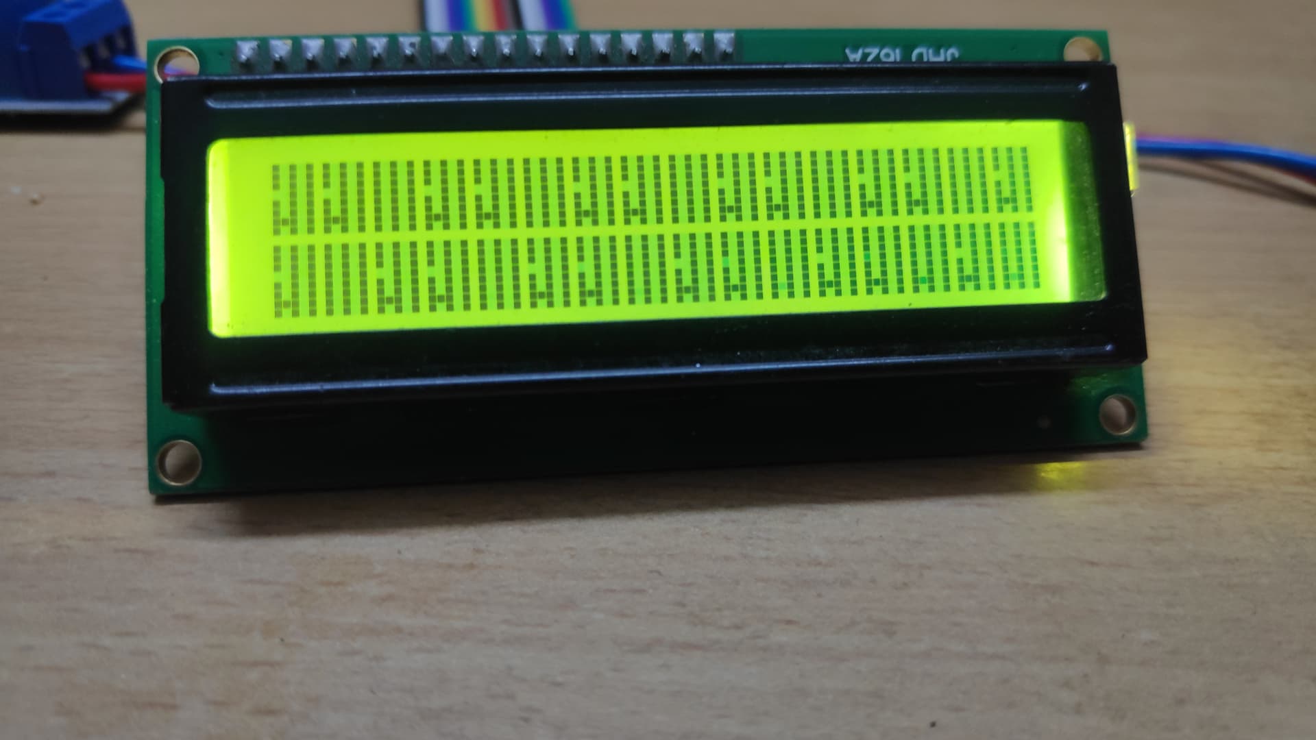
MAJOR PROBLEM FACED:
Actually when I turn on the power for arduino , the LCD works fine showing the favourable strings and the relays turn ON and bulb glows... After few minutes , there is a small strange / garbage character appears in the LCD along with string ..Then after strange/garbage characters proliferate and are piling up in the rows and my favourable required strings are replaced by those piled up strange characters..what to do....what is the problem and what is the solution.
I have not used i2c for lcd will that be a problem??

CODING:

#include <Keypad.h>

#include <LiquidCrystal.h>

#include <Wire.h>

const byte ROWS = 4;
const byte COLS = 4;
char keys[ROWS][COLS] = {
{'1', '2', '3', 'A'},
{'4', '5', '6', 'B'},
{'7', '8', '9', 'C'},
{'*', '0', '#', 'D'}
};
byte rowPins[ROWS] = {13, 12, 11, 10};
byte colPins[COLS] = {9, 8, 7, 6};
Keypad keypad = Keypad(makeKeymap(keys), rowPins, colPins, ROWS, COLS);
int keypadValue = 0;
String keypadString = "";

LiquidCrystal lcd(A0, A1, A2, A3, A4, A5);

int count = 0;
int display_value = 0;
int first = 0;
int second = 0;
int entering = 0;
int exiting = 0;

void setup()
{
pinMode(2, INPUT);
pinMode(3, INPUT);
pinMode(4, OUTPUT);
pinMode(5, OUTPUT);

lcd.begin(16, 2);
lcd.clear();
lcd.setCursor(0, 0);
lcd.print("PEOPLE INSIDE : ");

Serial.begin(9600);
}

void loop()
{
char key = keypad.getKey();
if(key != NO_KEY){
if(key == 'D'){
keypadValue = keypadString.toInt();
count = keypadValue;
keypadString = "";
}
else keypadString += key;
}

first = !digitalRead(3);
second = !digitalRead(2);

if(!second && !first && (entering == 3 || exiting == 3))
{
entering = 0;
exiting = 0;
}

if(first && entering != 3 && exiting != 3)
{
if(exiting == 0 )
{
entering = 1;
}
else
{
exiting = 2;
}
}

if(second && entering != 3 && exiting != 3)
{
if(entering == 0)
{
if(exiting == 0) exiting = 1;
}
else
{
entering = 2;
}
}

if(entering == 2)
{
count++;
entering = 3;
}

if(exiting == 2)
{
count--;
exiting = 3;
}

display_value = count != display_value ? count : display_value;

lcd.setCursor(0, 1);
lcd.print(" ");
lcd.setCursor(0, 1);
lcd.print(display_value);

Serial.print("People inside : ");
Serial.print(count);

Serial.print(" Lights : ");
Serial.print(count ? "ON" : "OFF");

Serial.print(" Entering : ");
Serial.print(entering);

Serial.print(" Exiting : ");
Serial.println(exiting);

digitalWrite(4, count > 0 ? LOW: HIGH);
digitalWrite(5, count > 0 ? LOW: HIGH);
}

Circuit connections:


Welcome to the forum

Please post your sketch, using code tags when you do

Just a quick thought:

String keypadString = "";

You're using String, which is generally frowned upon, because it has the tendency to cause spooky memory issues, which could cause something similar to your problem.

void loop()
{
char key = keypad.getKey();
if(key != NO_KEY){
if(key == 'D'){
keypadValue = keypadString.toInt();
count = keypadValue;
keypadString = "";
}
else keypadString += key;
}

In your loop(), you're appending to that string. If some stray input was turning up somehow, it would keep filling up your string until it fills up all the RAM.

I'm not at all sure, but as a test, maybe you could try commenting out the line:

// else keypadString += key;

This won't fix the problem, but if you upload the code and leave your circuit to sit for a few minutes, you'll find out if the problem has any connection to your String.

@theeccentricgenius Lacking a response to your question, I think it's quite possible adds12 is an AI bot assigned to the Arduino forum for the purpose of implementing change. In what direction, we may find out in the fullness of time.
But, maybe not.
@hari162001 I'm very sorry to say this, but your connection diagram is very hard to understand. If you have the ability, a schematic might be much more informative. If not, then all I can do is hazard a guess that you've got the Uno's onboard regulator overloaded, and it's not delivering the 5V that the LCD needs. That's consistent with failure over time, as the regulator heats up and begins to malfunction.
Best of luck.

2 Likes

adds12 will not be replying to anything as he/she has been suspended

5 Likes

Thanks

I have not used i2c for lcd will that be a problem???

No, since I see no evidence you have an I2C backpack for your display.

Posts 3 and 7 contain hints which might help you understand why there's so little traffic on this thread. We need more information about your circuit, and the present code you're using. Please use code tags for your code when you post it. It will look like this, for example:

  if (!second && !first && (entering == 3 || exiting == 3))  
  {
    entering = 0;
    exiting = 0;
  }

instead of
if (!second && !first && (entering == 3 || exiting == 3))
{
entering = 0;
exiting = 0;
}
That does two things. It makes it infinitely more readable in your post, and it means we can click on the "copy" button in the upper right hand corner to get a complete copy of your code to paste into our IDE for inspection.
As for my comment about a schematic, to understand your circuit it's imperative to be able to unambiguously assess your power supply and distribution. Multi-coloured wires going every which way simply don't suffice for that.
You don't need CAD, a picture of a pencil sketch on a sheet of paper is all that's really necessary. Show all devices, all connections, and list all part values/identifiers. Learning to communicate using schematics is a vital part of learning electronics as a whole.

first thing I see - 5V from the Arduino to 220 ohms, then to LED of display as well as two sensors and your relay module. So the last three items only ever see the voltage drop across the display backlight LED.
I'm assuming that's a schematic error now, and in fact your Arduino is powering

  • LCD
  • Backlight LED
  • Relay
  • 2x unlabeled sensors
    Power is by USB, I presume, since you show no power supply attached in your schematic.

However, one photo shows an adapter plugged into the UNO, and you reference a 5V AC-DC adapter. If that's the one, be advised that the barrel jack input on the UNO is for voltages > 7V. Supplying 5V to that connector runs your UNO at much less than 5V, if at all, and will be very problematic.

Sometimes when I used 9v battery also, I encountered this LCD crashing problem ...If I use 12v 1A adapter, then Arduino gets very very hot very quickly within few seconds that's I used 5v adapter of mobile charger..

I FOUND AN OBSERVATION:

  1. When I switch OFF the bulb switch(bulb not operated) and run the kit , everything works fine including LCD and relays also turning ON. No LCD crashing problem..

  2. but when switch ON bulb (bulb is operated) , after turning ON the kit, then only LCD crashing..

CONCLUSION: Until unless when the bulb is not operated, everything works fine including LCD and relays ..But when the bulb is switched (operated) , then LCD crashes as shown above figure..

I think there is no problem till the relay module all works fine including LCD, but there is LCD problem after the relay module( when bulb switch is operated)..

And while the bulb switch is operated , this LCD crashing garbage characters issue not occuring everytime, this problem occurs 2 to 3 times out of 7 times..

Very frustrating..,...some times LCD works fine, some time shows strange behaviour.....if LCD shows this strange behaviour everytime, then I can conclude that there is something wrong in my connections, but most of the times works fine without any issues......so what to do.....I want to make it as real time project by turning ON lights and Fan in room.

Please help me

Plug a well regulated 5V external power supply into the 5V pin of the Arduino, not the power plug or Vin. That will bypass the weak 5V regulator and the rated output of the external 5V supply will be availabe to the 5V peripherals.

1 Like

This topic was automatically closed 180 days after the last reply. New replies are no longer allowed.