Im making this project for me to learn on my own.
Its a timeout box for your phone during study sessions.
But the LCD is not working as intended but when i put it together and coded it in tinkercad first it all worked fine
Im trying to no have as much big
parts in this project so instead of using a potentiometer im using a resistor( 1.2 kΩ) for a more simple build.
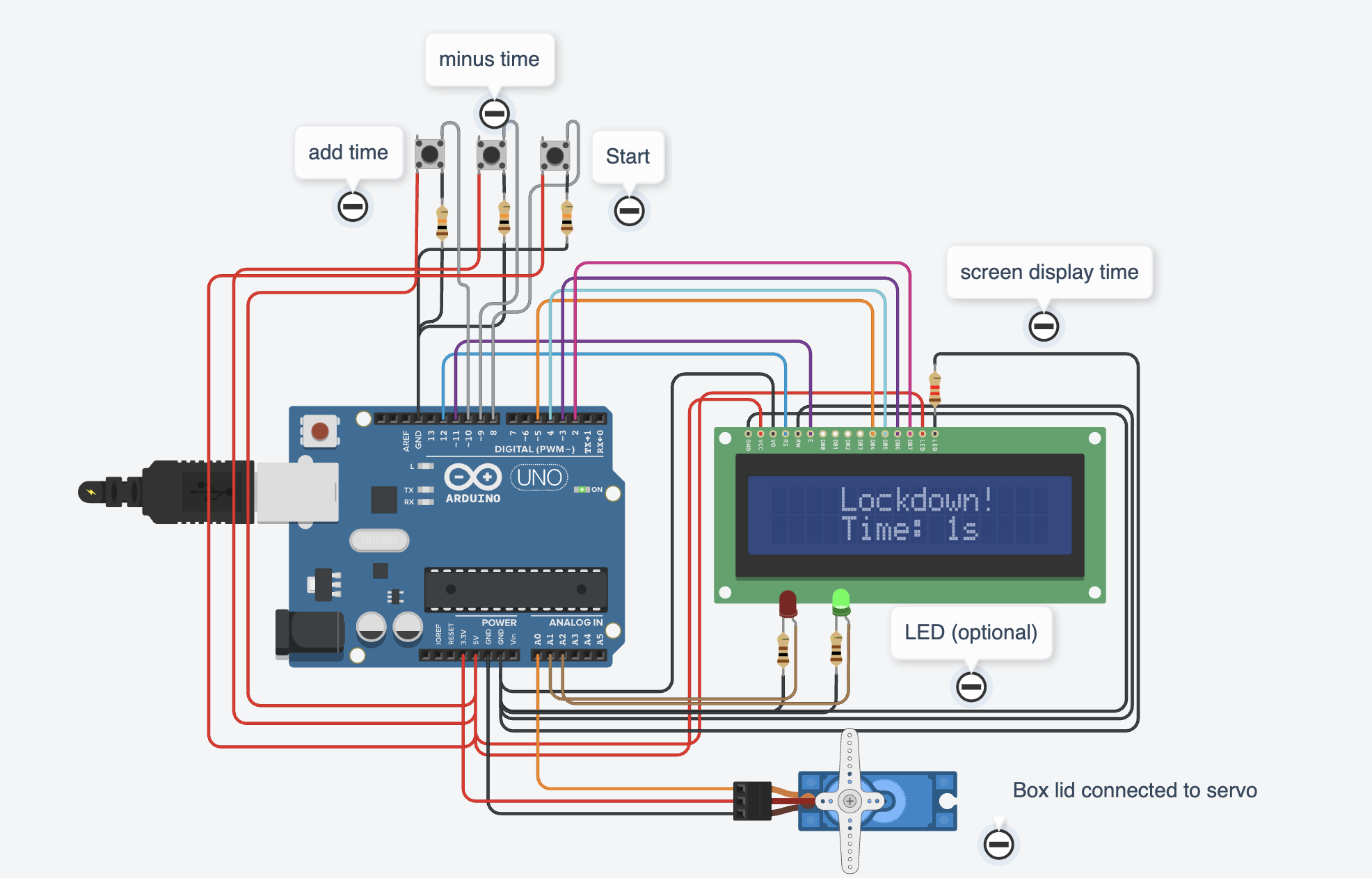
Image of the circuit:

image of wiring on tinkercad:

This wiring is also just the lcd with the other components removed
full code (contains the code for the other components) :
#include<LiquidCrystal.h>
#include <Servo.h>

LiquidCrystal lcd(12, 11, 5, 4, 3, 2);
Servo servo_A0;

int time = 1; // Default time is 1
const int buttonPinUp = 10;     // Button to add time
const int buttonPinDown = 9;    // Button to minus time
const int buttonStart = 8;      // Button to start timer
int buttonStateUp = LOW;        // Default state of add button
int buttonStateDown = LOW;      // Default state of minus button
int buttonStartState = LOW;     // Default state of start button
const int Red = A1;				// Pin for red led
const int Green = A2;			// Pin for green led
const int maxTime = 60;         // Max time set
bool timerRunning = false;      // Flag to check if the timer is running

// Array to store display messages
const char* displayMessages[] = {
  "    Lockdown!",  // Message for line 1
  "Time: ",         // Prefix for line 2
  "s",              // Second indicator
  " "               // Space for alignment
};

// function for adding time
void increaseTime() {
  if (time < maxTime) {
    time = time + 1;
  }
}


// function for deducting time
void decreaseTime() {
  if (time > 1) {
    time = time - 1;
  }
}

void setup()
{
  lcd.begin(16, 2); // Activate the LCD
  pinMode(buttonPinUp, INPUT);		//receive input from add button
  pinMode(buttonPinDown, INPUT);	//receive input from minus button
  pinMode(buttonStart, INPUT); 		//receive input from start
  pinMode(Red, OUTPUT);				//send output to red led
  pinMode(Green, OUTPUT);			//send output to green led

  // servo set to 90 degrees
  servo_A0.attach(A0, 500, 2500);
  servo_A0.write(90);
}

void loop()
{
  // LCD timer menu  		   // timerRunning == false as !timerRunning
  if (!timerRunning) { 		   // if timerRunning is false then LCD menu is activated
    digitalWrite(Red, LOW);
    digitalWrite(Green, HIGH);

    lcd.setCursor(0, 0);
    lcd.print(displayMessages[0]); // array for message

    lcd.setCursor(4, 1);
    lcd.print(displayMessages[1]); // array for prefix
    lcd.print(time);


    if (time < 10) {
      lcd.setCursor(11, 1);
      lcd.print(displayMessages[2]); // array for "s"
      lcd.setCursor(12, 1);
      lcd.print(displayMessages[3]); // array for space

    }
    if (time > 9) {
      lcd.setCursor(12, 1);
      lcd.print(displayMessages[2]); // array for "s"
    }

    // When button add is pressed
    buttonStateUp = digitalRead(buttonPinUp);

    if (buttonStateUp == HIGH) {
      increaseTime();
      delay(200); // Process time
    }

    // When button minus is pressed
    buttonStateDown = digitalRead(buttonPinDown);

    if (buttonStateDown == HIGH) {
      decreaseTime();
      delay(200); // Process time
    }
  }

  // When start button is pressed
  buttonStartState = digitalRead(buttonStart);

  if (buttonStartState == HIGH && !timerRunning) {
    lcd.clear(); // Clear the LCD
    servo_A0.write(0); // Lock the box
    digitalWrite(Red, HIGH);
    digitalWrite(Green, LOW);
    timerRunning = true; // Start timer
    delay(200); // Process time

    // Countdown timer
    for (int i = time; i >= 0; i--) {
      lcd.setCursor(0, 0);
      lcd.print("Time Remaining:");
      lcd.setCursor(0, 1);
      lcd.print("    ");
      lcd.setCursor(4, 1);
      lcd.print(i);
      lcd.print(" seconds");
      delay(1000);
    }

    // Timer has finished
    lcd.clear();
    lcd.setCursor(0, 0);
    lcd.print("Timer Complete!");
    servo_A0.write(90);
    digitalWrite(Red, LOW);
    digitalWrite(Green, HIGH);
    delay(1700);
    lcd.setCursor(0, 0);
    lcd.print("                ");
    timerRunning = false; // timer is off
  }
}
image of the full circuit:
I would like to know how to fix this and the mistake i made at this moment.