MAX7219 Led Module 8-Digit 7 Segment showing gibrish

I connect to my Arduino UNO a 4 digit led screen with chip TM1637 that works fine.
I then change the module to MAX7219 with using the "LedControl.h".
Using simple example from the library, the screen shows gibrish and not the right output. Its also freeze or turned off randomly.
I think I am not doing something right.
Do I need a resistor


here?

Please, post your sketch that is driving the MAX7219 based 8-digit CC-type 7-segment Display Unit.

You will want one resistor per LED segment (eight resistors for A, B, C, D, E, F, G, DP) to give all segments equal brightness. incorrect... this only is for 7-seg without a controller... see post #4

1 Like

MAX7219 driven display does not require any current limiting resistor for the segments. That Rex1 (Fig-1) resistor controls the current along with brightness register of the chip.
max7219-4Digit
Figure-1:

//We always have to include the library
#include "LedControl.h"

/*
 Now we need a LedControl to work with.
 ***** These pin numbers will probably not work with your hardware *****
 pin 12 is connected to the DataIn 
 pin 11 is connected to the CLK 
 pin 10 is connected to LOAD 
 We have only a single MAX72XX.
 */
LedControl lc=LedControl(2,3,4,1);

/* we always wait a bit between updates of the display */
unsigned long delaytime=250;

void setup() {
  /*
   The MAX72XX is in power-saving mode on startup,
   we have to do a wakeup call
   */
  lc.shutdown(0,false);
  /* Set the brightness to a medium values */
  lc.setIntensity(0,8);
  /* and clear the display */
  lc.clearDisplay(0);
}


/*
 This method will display the characters for the
 word "Arduino" one after the other on digit 0. 
 */
void writeArduinoOn7Segment() {
  lc.setChar(0,0,'a',false);
  delay(delaytime);
  lc.setRow(0,0,0x05);
  delay(delaytime);
  lc.setChar(0,0,'d',false);
  delay(delaytime);
  lc.setRow(0,0,0x1c);
  delay(delaytime);
  lc.setRow(0,0,B00010000);
  delay(delaytime);
  lc.setRow(0,0,0x15);
  delay(delaytime);
  lc.setRow(0,0,0x1D);
  delay(delaytime);
  lc.clearDisplay(0);
  delay(delaytime);
} 

/*
  This method will scroll all the hexa-decimal
 numbers and letters on the display. You will need at least
 four 7-Segment digits. otherwise it won't really look that good.
 */
void scrollDigits() {
  for(int i=0;i<13;i++) {
    lc.setDigit(0,3,i,false);
    lc.setDigit(0,2,i+1,false);
    lc.setDigit(0,1,i+2,false);
    lc.setDigit(0,0,i+3,false);
    delay(delaytime);
  }
  lc.clearDisplay(0);
  delay(delaytime);
}

example video

Try to follow this tutorial to see 4567 on the display unit. This is a test sketch. You can then use the LedControl.h Library.
1. Connect your display unit as follows with Arduino UNO using SPI Port.

UNO              Display Module
5V               Vcc
GND              GND
10 (ss)          CS
11 (MOSI)        DI
13  (SCK)        CLK

2. Upload the following sketch.

#include<SPI.h>
byte registerAddress[] = {0x0C, 0x09, 0x0A, 0x0B}; //control registers of MAX7219, see data sheets
byte registerData[] = {0x01, 0x00, 0x01, 0x07};
//normal modeo; no-decode;intensity;8-digit scan
byte dataArray[8];  //to hold cc-codes (no-decode format)
byte digitAddress[] = {0x01, 0x02, 0x03, 0x04, 0x05, 0x06, 0x07, 0x08};//DP0-DP7
byte lupTable[] = {0x7E, 0x30, 0x6D, 0x79, 0x33, 0x5B, 0x5F, 0x70,
                   0x7F, 0x7B, 0x77, 0x1F, 0x4E, 0x3D, 0x4F, 0x47
                  }; //0, 1, ...., E, F ; no-decode cc-code see data sheets

void setup()
{
  pinMode(10, OUTPUT);  //LOAD Pin of MAX7219
  //-------------------
  SPI.begin();
  // bitSet(SPCR, 4);              //UNO is Master SPI
  //  SPI.setBitOrder(MSBFIRST);    //MSB_bit will be transferred first
  SPI.setClockDivider(SPI_CLOCK_DIV128); //TX rate = 16MHz/128 = 125 kbit
  //  SPI.setDataMode(SPI_MODE1);//MOSI is sampled at the rising edge of CLK
  //------------------------------------------------
  digitalWrite(10, LOW);      //Low at LOAD pin
  //---- dataArray update-----------------------------
  dataArray[0] = lupTable[4];   //no-decode cc-code of digit-4
  dataArray[1] = lupTable[5];   //n0-decode cc-code of digit-5
  dataArray[2] = lupTable[6];   //no-decode cc-code of digit-6
  dataArray[3] = lupTable[7];   //no-decode cc-code of digit-7
  //-------------------------------------------------


  //---keep intializing the Mode of Operation------------
  for (int i = 0; i < 4; i++)
  {
    SPI.transfer(registerAddress[i]);
    SPI.transfer(registerData[i]);
    digitalWrite(10, LOW);
    digitalWrite(10, HIGH); //assert LH/LL on LOAD pin
    digitalWrite(10, LOW);
  }

  //--keep transferring the result/data----------------------
  for (int i = 0; i < 4; i++)
  {
    SPI.transfer(digitAddress[i]); //DPX position
    SPI.transfer(dataArray[i]);   //shows 4 5 6 7 on display
    digitalWrite(10, LOW);
    digitalWrite(10, HIGH);       //assert LH/LL on LOAD pin
    digitalWrite(10, LOW);
  }
}

void loop()
{

}

3. Check that 4567 has appeared on the display module.
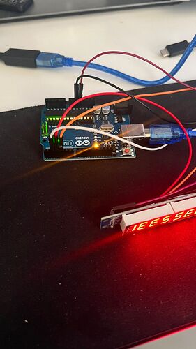
This is what I am getting with your code.
Why I have gibrish on the left side? RIght side shows 4567

The sketch is working. Now, it is the question of display orientation. Take Fig-1 of post #4 as reference and use DMM/AVM to find DP0, DP1, ....., DP7 of your Display Unit. Your dipslay is good and functional. You see garbage on 4-digit as my sketch sends data for the DP0-DP3 positions.

Any Idea why ledControl.h isnt workin properly here?

Maybe you can help me with a code that can display numbers?
I need to display numbers from -10000 to + 10000

your sketch derived from example have missing something important.
will you try now the example sketch?

The main problem is that for the first loop it can works fine but then on second/third loop its starts to show garbage.
Also many times the screen just freeze and not responding.
I tried with different unit but same results.

Carry out the following Tutorial of net and check that your display unit shows the message correctly and then I will try to show you how convert your display into a Up Counter and then a Down Counter.

not tested

#include "LedControl.h"

/*
  pin 12 is DataIn
  pin 11 is CLK
  pin 10 is LOAD
*/
LedControl lc(12, 11, 10, 1); // only a single MAX72XX.
int Num = -10000;


void setup() {
  lc.shutdown(0, false);
  lc.setIntensity(0, 8);
  lc.clearDisplay(0);
}

void loop() {
  showInteger(Num);
  delay(300);
  lc.clearDisplay(0);
  Num++;
}

void showInteger(int n) {
  char buffer[9];
  sprintf(buffer, "%8d", n);
  for (byte d=0; d<8; d++)lc.setChar(0, d, buffer[d], false);
}

Simpler version

void showInteger(int n) {
  char buffer[9];
  sprintf(buffer, "%8d", n);
  for (byte d=0; d<8; d++)
    lc.setChar(0, d, buffer[d], false);
}
1 Like

without leading zeros?

Yes, leading blanks. Has @amir_bbb asked for leading zeros? I did not see that.

For leading zeros, use "%08d".

1 Like

Ledaing zero looks no good for decimal display.
0, 1, ....,9, 10, 11, ..........., 9999, 10000, 9999, ......., 9, 8, ....., 1, 0, -1, ......., -9999, -10000

This module is totally unreelable or the library is unreelable.
I can make it works for time to time, but most of the time i am getting garbage on the display.
Sometime it turns on and sometime not.

I tried the TM1637 and it works fine.

What is going on here?