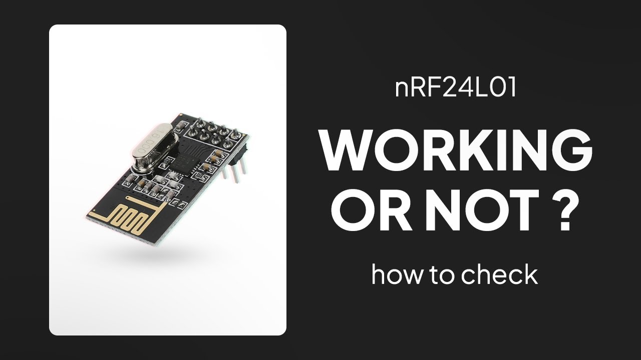
As described in the RF24 Common Issues Guide, radio modules, especially the PA+LNA versions, are highly reliant on a stable power source. The 3.3V output from Arduino is not stable enough for these modules in many applications. While they may work with an inadequate power supply, you may experience lost packets or reduced reception compared to modules powered by a more stable source.
Symptoms of Power Issues:
Radio module performance may improve when touched, indicating power stability issues.
These issues are often caused by the absence of a capacitor, a common cost-saving omission by some manufacturers.
Temporary Patch:
Add Capacitors: Place capacitors close to the VCC and GND pins of the radio module. A 10uF capacitor is usually sufficient, but the exact value can depend on your circuit layout.
Use Low ESR Capacitors: Capacitors with low Equivalent Series Resistance (ESR) are recommended, as they provide better power stability and performance.
Adding the appropriate capacitors can greatly improve the reliability of your RF24 module by ensuring a stable power supply, thus minimizing packet loss and enhancing overall performance. A separate power supply for the radios is the best solution.
transmitter Nano and NRF24L01 powered from USB (no capacitors)
// Nano > NRF24L01 transmitter test using a text string

// RP2040 connections
// RP2040 SPIO_SCK pin GP18 goes to NRF24L10_pin SCK
// RP2040 SPIO_RX pin GP16 goes to NRF24L10_pin MISO
// RP2040 SPIO_TX pin GP19 goes to NRF24L10_pin MOSI
// RP2040 pin SPIO_CSn GP17 to NRF24L10 CSN
// RP2040 pin GP20 to NRF24L10 CE
// RP2040 GND and 3.3V to NRF24L10  GND and VCC

// Leonardo connections ???
// Leonardo ICSP SCK  pin 15 to NRF24L10_pin SCK
// Leonardo ICSP MISO pin 14 to NRF24L10_pin MISO
// Leonardo ICSP MOSI pin 16 to NRF24L10_pin MOSI
// Leonardo pin 10 to NRF24L10 CSN
// Leonardo pin 9  to NRF24L10 CE
// Leonardo GND and 3.3V to NRF24L10  GND and VCC

// ESP8266 connections
// ESP8266 SCK pin GPIO14 goes to NRF24L10_pin SCK
// ESP8266 MISO pin GPIO12 goes to NRF24L10_pin MI
// ESP8266 MOSI pin GPIO13 goes to NRF24L10_pin MO
// NRF24L10 CE to ESP8266 pin GPIO4
// NRF24L10 CSN to ESP8266 pin GPIO5

// UNO/Nano connections
// arduino MOSI pin 11 goes to NRF24L10_pin MOSI
// arduino MISO pin 12 goes to NRF24L10_pin MI
// arduino SCK  pin 13 goes to NRF24L10_pin SCK
// NRF24L10 CE to arduino pin 9
// NRF24L10 CSN to arduino pin10
// NRF24L10 VCC to 3.3V and GND to GND


#include <SPI.h>
#include "RF24.h"
#include <printf.h>

#define CE_PIN 9
#define CSN_PIN 10

bool radioNumber = 0;
RF24 radio(CE_PIN, CSN_PIN, 100000);

byte addresses[][6] = { "1Node", "2Node" };

void setup() {
  Serial.begin(115200);
  delay(2000);
  Serial.println("\n\nNano > NRF24L01 transmit text");
  radio.begin();
  if (radio.isChipConnected())
    Serial.println("Transmitter NF24 connected to SPI");
  else {
    Serial.println("NF24 is NOT connected to SPI");
    while (1)
      ;
  }
  radio.setChannel(125);
  radio.setPALevel(RF24_PA_MIN);
  printf_begin();  // needed only once for printing details
  radio.printDetails();
  radio.powerUp();
  radio.setDataRate(RF24_1MBPS);
  //radio.setDataRate(RF24_250KBPS);

  if (radioNumber) {
    radio.openWritingPipe(addresses[1]);
    radio.openReadingPipe(1, addresses[0]);
  } else {
    radio.openWritingPipe(addresses[0]);
    radio.openReadingPipe(1, addresses[1]);
  }
  radio.stopListening();
  //radio.setPayloadSize(sizeof(Struct1));
}

// loop transmiting data packet
void loop() {
  static char testString[10] = "text 0";
  radio.write(testString, sizeof(testString));
  Serial.print("transmit ");
  Serial.println(testString);
  delay(1000);
  testString[5]++;
}
nano receiver (Nano powered from USB - NRF24L01 from external 3.3V from a ESP32 with 100uF capacitor)
//  Nano > NRF24L01 receiver test using a text string

// UNO/Nano connections
// arduino MOSI pin 11 goes to NRF24L10_pin MOSI
// arduino MISO pin 12 goes to NRF24L10_pin MI
// arduino SCK  pin 13 goes to NRF24L10_pin SCK
// NRF24L10 CE to arduino pin 9
// NRF24L10 CSN to arduino pin10
// NRF24L10 VCC to 3.3V and GND to GND

#include <SPI.h>
#include <RF24.h>
#include <printf.h>

#define CE_PIN 9
#define CSN_PIN 10

bool radioNumber = 1;
const uint8_t pipes[][6] = { "1Node", "2Node" };

RF24 radio(CE_PIN, CSN_PIN);

char dataReceived[10];  // this must match dataToSend in the TX
bool newData = false;

//===========

void setup() {
  Serial.begin(115200);
  delay(1000);
  Serial.println("Nano > NRF24L01 Receive text");
  radio.begin();
  if (radio.isChipConnected())
    Serial.println("Receiver NF24 connected to SPI");
  else {
    Serial.println("NF24 is NOT connected to SPI");
    while (1)
      ;
  }
  radio.setChannel(125);
  radio.setDataRate(RF24_1MBPS);
  //radio.setDataRate(RF24_250KBPS);
   printf_begin();             // needed only once for printing details
   radio.printDetails();       // (smaller) function that prints raw register values
   radio.printPrettyDetails(); // (larger) function that prints human readable data
  if (!radioNumber) {
    radio.openWritingPipe(pipes[0]);
    radio.openReadingPipe(1, pipes[1]);
  } else {
    radio.openWritingPipe(pipes[1]);
    radio.openReadingPipe(1, pipes[0]);
  }
  radio.startListening();
  // radio.setPayloadSize(sizeof(Struct1));
}

//=============

void loop() {
  if (radio.available()) {
    char testString[10] = "";
    radio.read(testString, sizeof(testString));
    Serial.print("Test string:      ");
    Serial.println(testString);
  }
}
transmitter serial monitor output
Nano > NRF24L01 transmit text
Transmitter NF24 connected to SPI
SPI Speedz	= 0 Mhz
STATUS		= 0x0e RX_DR=0 TX_DS=0 MAX_RT=0 RX_P_NO=7 TX_FULL=0
RX_ADDR_P0-1	= 0xe7e7e7e7e7 0xc2c2c2c2c2
RX_ADDR_P2-5	= 0xc3 0xc4 0xc5 0xc6
TX_ADDR		= 0xe7e7e7e7e7
RX_PW_P0-6	= 0x20 0x20 0x20 0x20 0x20 0x20
EN_AA		= 0x3f
EN_RXADDR	= 0x03
RF_CH		= 0x7d
RF_SETUP	= 0x01
CONFIG		= 0x0e
DYNPD/FEATURE	= 0x00 0x00
Data Rate	= 1 MBPS
Model		= nRF24L01+
CRC Length	= 16 bits
PA Power	= PA_MIN
ARC		= 0
transmit text 0
transmit text 1
transmit text 2
transmit text 3
transmit text 4
transmit text 5
transmit text 6
transmit text 7
transmit text 8
transmit text 9
transmit text :
transmit text ;
transmit text <
transmit text =
transmit text >
transmit text ?
transmit text @
transmit text A
transmit text B
transmit text C
receiver serial output
Nano > NRF24L01 Receive text
Receiver NF24 connected to SPI
SPI Speedz	= 0 Mhz
STATUS		= 0x0e RX_DR=0 TX_DS=0 MAX_RT=0 RX_P_NO=7 TX_FULL=0
RX_ADDR_P0-1	= 0xe7e7e7e7e7 0xc2c2c2c2c2
RX_ADDR_P2-5	= 0xc3 0xc4 0xc5 0xc6
TX_ADDR		= 0xe7e7e7e7e7
RX_PW_P0-6	= 0x20 0x20 0x20 0x20 0x20 0x20
EN_AA		= 0x3f
EN_RXADDR	= 0x03
RF_CH		= 0x7d
RF_SETUP	= 0x07
CONFIG		= 0x0e
DYNPD/FEATURE	= 0x00 0x00
Data Rate	= 1 MBPS
Model		= nRF24L01+
CRC Length	= 16 bits
PA Power	= PA_MAX
ARC		= 0
SPI Frequency		= 0 Mhz
Channel			= 125 (~ 2525 MHz)
Model			= nRF24L01+
RF Data Rate		= 1 MBPS
RF Power Amplifier	= PA_MAX
RF Low Noise Amplifier	= Enabled
CRC Length		= 16 bits
Address Length		= 5 bytes
Static Payload Length	= 32 bytes
Auto Retry Delay	= 1500 microseconds
Auto Retry Attempts	= 15 maximum
Packets lost on
    current channel	= 0
Retry attempts made for
    last transmission	= 0
Multicast		= Disabled
Custom ACK Payload	= Disabled
Dynamic Payloads	= Disabled
Auto Acknowledgment	= Enabled
Primary Mode		= TX
TX address		= 0xe7e7e7e7e7
pipe 0 ( open ) bound	= 0xe7e7e7e7e7
pipe 1 ( open ) bound	= 0xc2c2c2c2c2
pipe 2 (closed) bound	= 0xc3
pipe 3 (closed) bound	= 0xc4
pipe 4 (closed) bound	= 0xc5
pipe 5 (closed) bound	= 0xc6
Test string:      text 0
Test string:      text 1
Test string:      text 2
Test string:      text 3
Test string:      text 4
Test string:      text 5
Test string:      text 6
Test string:      text 7
Test string:      text 8
Test string:      text 9
Test string:      text :
Test string:      text ;
Test string:      text <
Test string:      text =
Test string:      text >
Test string:      text ?
Test string:      text @
Test string:      text A
Test string:      text B
Test string:      text C
Test string:      text D
Test string:      text E
Test string:      text F
Test string:      text G
Test string:      text H
without the external power supply the receiver reception was very intermittent
EDIT: ESP32 receiver (no capacitors)
ESP32 > NRF24L01 Receive text
Receiver NF24 connected to SPI
SPI Speedz	= 10 Mhz
STATUS		= 0x0e RX_DR=0 TX_DS=0 MAX_RT=0 RX_P_NO=7 TX_FULL=0
RX_ADDR_P0-1	= 0xe7e7e7e7e7 0xc2c2c2c2c2
RX_ADDR_P2-5	= 0xc3 0xc4 0xc5 0xc6
TX_ADDR		= 0xe7e7e7e7e7
RX_PW_P0-6	= 0x20 0x20 0x20 0x20 0x20 0x20
EN_AA		= 0x3f
EN_RXADDR	= 0x03
RF_CH		= 0x7d
RF_SETUP	= 0x07
CONFIG		= 0x0e
DYNPD/FEATURE	= 0x00 0x00
Data Rate	= 1 MBPS
Model		= nRF24L01+
CRC Length	= 16 bits
PA Power	= PA_MAX
ARC		= 0
Test string:
Test string:      text 0
Test string:      text 1
Test string:      text 2
Test string:      text 3
Test string:      text 4
Test string:      text 5
Test string:      text 6
Test string:      text 7
Test string:      text 8
Test string:      text 9
Test string:      text :
Test string:      text ;
Test string:      text <
Test string:      text =
Test string:      text >
Test string:      text ?
Test string:      text @
Test string:      text A
Test string:      text B
Test string:      text C
Test string:      text D
Test string:      text E
Test string:      text F
Test string:      text G
Test string:      text H
all that shows is that the Nano SPI is communicating with the NRF24L01 which will work OK just off the nano power supply
did you get any communication? which is when NRF24 power supply problems occur
how did you power the nanos? USB?
did the nano and NRF24L01 have a common GNDs?
when I tested the nano and an external power supply the nano was powered from USB, the NRF24 from external power and the nano and NRF24 shared a command GND
did you try the programs @Paul_KD7HB suggested in post 27?
or the programs I uploaded in post 28?
You seem to have the NRF module connected directly to the Nano and Uno without going through the daughter board. The NRF module needs 3.3v signals and not the 5v signals coming from the Nano and Uno. You need that daughter board or use a level shifter to convert the 5v signals to the 3.3v signals the module requires.
The other alternative would be to use Arduino that use 3.3v logic like a Due or Arduino Pro Micro (8Mhz) or something similar.
I am speaking from past experiences. I had the 16Mhz pro Micro (5v) wired up (correctly) to the NRF24L01 module and it wouldn’t work. But once I swapped to the Pro Micro 8Mhz (3.3v) it worked just fine.
I also now have a bunch of 16Mhz Pro Micros that I don’t have a use for, because I bought them in bulk for my projects.