Hi I need help with hardware and software.
The project consists of 10 emg electrodes that are connected to 10 pcs of 3,5mm jack inputs. I need to get each value isolated so the signal is clear to each electrode. Right now I get random values that are not isolated and pin1 is creating values.
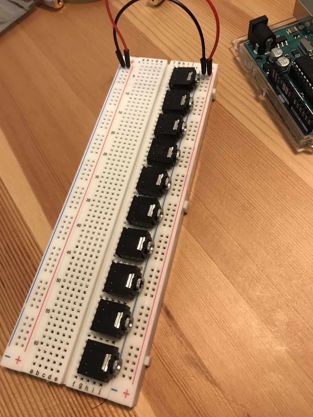
hardware: I use 3,5mm stereo jack sockets for pcb board (picture) in breadboard and these have shorter pins. I don't know if it works right now because the code may be bad as well. How to check that?
How to arrange the setup for 10 jack sockets and connect them (picture)? Do I have to connect 2 pins for one jack socket (power and earth)? It doesn't allign with the code (pinMode is for setting one pin). Do I have to use resistors and analog pins as well?
void setup() {

// initialize the serial communication:

Serial.begin(9600);

pinMode(2, INPUT); // Setup for leads off detection LO +

pinMode(3, INPUT); // Setup for leads off detection LO +

pinMode(4, INPUT); // Setup for leads off detection LO +

pinMode(5, INPUT); // Setup for leads off detection LO +

pinMode(6, INPUT); // Setup for leads off detection LO +

pinMode(7, INPUT); // Setup for leads off detection LO +

pinMode(8, INPUT); // Setup for leads off detection LO +

pinMode(9, INPUT); // Setup for leads off detection LO +

pinMode(10, INPUT); // Setup for leads off detection LO +

pinMode(11, INPUT); // Setup for leads off detection LO -

}

void handlePin(int pin) {

if (digitalRead(pin) == 1) {

Serial.print(analogRead(pin));

} else {

Serial.print("0");

}

Serial.print("\t");

}

void loop() {

handlePin(2);

handlePin(3);

handlePin(4);

handlePin(5);

handlePin(6);

handlePin(7);

handlePin(8);

handlePin(9);

handlePin(10);

handlePin(11);

handlePin(12);

Serial.println("");

delay(10);

}
Just defining a pin as an input with nothing connected to it is known as having a floating pin, and yes it will return a random value because it acts like an antenna and picks up interference.
A photograph of a solderless bread board full of unconnected sockets is not going to do much to help us.
There is no need to use a space between every line of code, in fact it is quite annoying.
If you use for loops then you code can be cut down very considerably in size.
void setup() {
// initialize the serial communication:
Serial.begin(9600);
for(int i = 2; i <= 11; i++){
      pinMode(i, INPUT_PULLUP); // Setup for leads off detection LO +
    }
}

void handlePin(int pin) {
if (digitalRead(pin) == LOW) {
   Serial.print(analogRead(pin));
} else {
   Serial.print("0");
}
  Serial.println("");
}

void loop() {
for(int i = 2; i <= 11; i++){ // your code said to handle pins up to 12 but you haven"t declared pin 12.
     handlePin(i);
}
Serial.println("");
delay(10);
}
Not that the code makes much sense of course because we have no idea about what the nature of these sensors are.
Well your code uses an analogue read so I would expect some analogue connections. Problem is you only have 6 of them on an Arduino so you will have to use a multiplexer as well.
What "EMG electrodes" are you using that can be read with an Ardinuo analog input? Please post a link to them.
This eliminates about half of the analog signal range:
if (digitalRead(pin) == LOW) {
   Serial.print(analogRead(pin));
EMG voltages are tiny, and a differential amplifier with neutral reference input is used to increase the signal level.
To reduce pickup of electrical noise from the environment, the cables and connections must all be shielded. A breadboard will not work. The electrode jacks need be in a closed metal box, with the box connected to shield ground.
No idea which EMG sensor you are using, but with 10 wired ones it will be a mess mechanically - and most probably electrically as well (depends on particular sensor schematics, but it's hard to isolate inputs from outputs to a degree where such setup won't mess things up - every few microvolts count). Also, there is next to no point in reading them as digital ones - signals are analog in their nature, digital reading would perform thresholding in an uncontrollable way so your sensitivity may end up anywhere without means to change it.
If you are determined to use wires - you need something with 10 analog inputs. Or you can use wireless ones (I obviously recommend uMyo in that role), although 10 is still a lot so not sure if readings will be all good, need to test that