32*8 RGB Display, 17 rows working, the rest are not

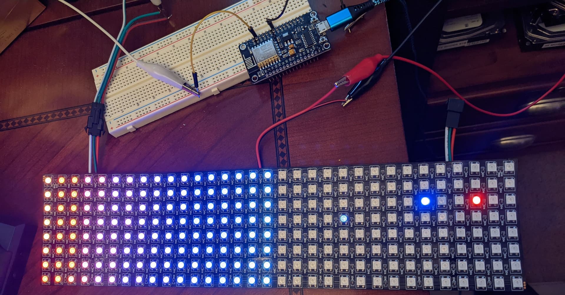
I downloaded some sample code to display some scrolling text. The first 17 rows are lighting up, the rest don't work. I'm wondering if I am not setting this up correctly:

Adafruit_NeoMatrix matrix = Adafruit_NeoMatrix(32, 8, PIN,
NEO_MATRIX_TOP + NEO_MATRIX_LEFT +
NEO_MATRIX_COLUMNS + NEO_MATRIX_ZIGZAG,
NEO_GRB + NEO_KHZ800);

Video of the issue:

I am using a ESP8266 board.
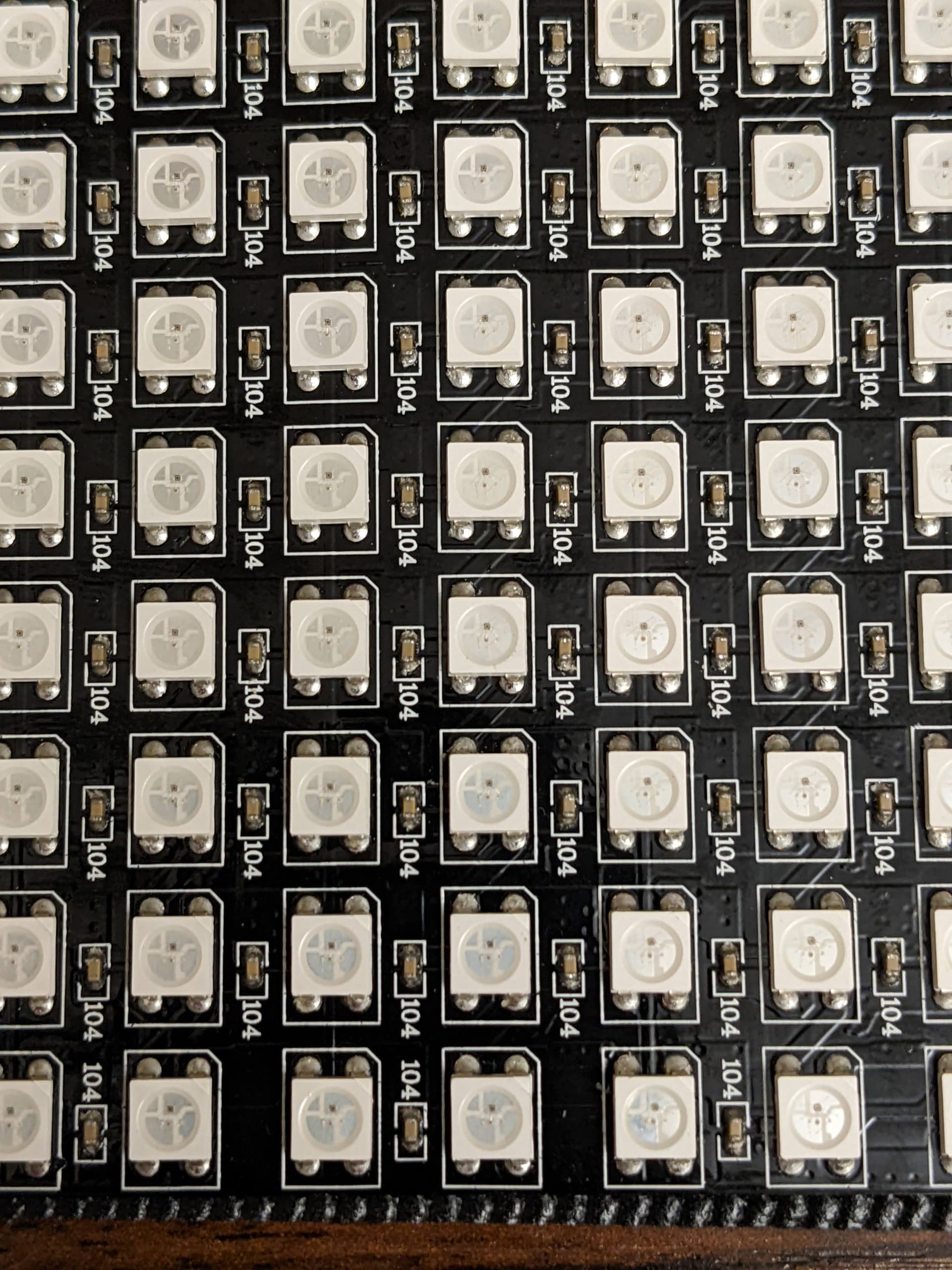
The LED Matrix description on Amazon is:

BTF-LIGHTING WS2812B ECO RGB Alloy Wires 5050SMD Individual Addressable 8X32 256 Pixels LED Matrix Flexible FPCB Full Color Works with K-1000C,SP107E,etc Controllers Image Video Text Display DC5V

#include <Adafruit_GFX.h>
#include <Adafruit_NeoMatrix.h>
#include <Adafruit_NeoPixel.h>
#ifndef PSTR
 #define PSTR // Make Arduino Due happy
#endif

#define PIN 4

// MATRIX DECLARATION:
// Parameter 1 = width of the matrix
// Parameter 2 = height of the matrix
// Parameter 3 = pin number (most are valid)
// Parameter 4 = matrix layout flags, add together as needed:
//   NEO_MATRIX_TOP, NEO_MATRIX_BOTTOM, NEO_MATRIX_LEFT, NEO_MATRIX_RIGHT:
//     Position of the FIRST LED in the matrix; pick two, e.g.
//     NEO_MATRIX_TOP + NEO_MATRIX_LEFT for the top-left corner.
//   NEO_MATRIX_ROWS, NEO_MATRIX_COLUMNS: LEDs are arranged in horizontal
//     rows or in vertical columns, respectively; pick one or the other.
//   NEO_MATRIX_PROGRESSIVE, NEO_MATRIX_ZIGZAG: all rows/columns proceed
//     in the same order, or alternate lines reverse direction; pick one.
//   See example below for these values in action.
// Parameter 5 = pixel type flags, add together as needed:
//   NEO_KHZ800  800 KHz bitstream (most NeoPixel products w/WS2812 LEDs)
//   NEO_KHZ400  400 KHz (classic 'v1' (not v2) FLORA pixels, WS2811 drivers)
//   NEO_GRB     Pixels are wired for GRB bitstream (most NeoPixel products)
//   NEO_GRBW    Pixels are wired for GRBW bitstream (RGB+W NeoPixel products)
//   NEO_RGB     Pixels are wired for RGB bitstream (v1 FLORA pixels, not v2)

//Adafruit_NeoMatrix matrix = Adafruit_NeoMatrix(32, 8, PIN,
//  NEO_MATRIX_TOP     + NEO_MATRIX_LEFT +
//  NEO_MATRIX_ROWS + NEO_MATRIX_ZIGZAG,
//  NEO_GRB            + NEO_KHZ800);

Adafruit_NeoMatrix matrix = Adafruit_NeoMatrix(32, 8, PIN,
  NEO_MATRIX_TOP     + NEO_MATRIX_LEFT +
  NEO_MATRIX_COLUMNS + NEO_MATRIX_ZIGZAG,
  NEO_GRB            + NEO_KHZ800);
  
const uint16_t colors[] = {
  matrix.Color(255, 0, 0), matrix.Color(0, 255, 0), matrix.Color(0, 0, 255) };

void setup() {
  Serial.begin(38400);
  matrix.begin();
  matrix.setTextWrap(false);
  matrix.setBrightness(100);
  matrix.setTextColor(colors[0]);
}

int x    = matrix.width();
int pass = 0;

void loop() {
  Serial.println (x);
  matrix.fillScreen(0);
  matrix.setCursor(x, 0);
  matrix.print(F("123456789"));
  if(--x < -36) {
    x = matrix.width();
    if(++pass >= 3) pass = 0;
    matrix.setTextColor(colors[pass]);
  }
  matrix.show();
  delay(100);
}

Welcome to the forum

Please post your code here as many users will not bother to visit another site to see it

My first guess is a break in the data line. Examine the traces between the 17th and 18th columns. Use a magnifier. Use a microscope if you have one.

Those are columns, not rows…
Please post your code here in code tags.

Thanks

I edited the first post to include the code

How is this powered?

External power supply, 10Amps. I have the ground going to the matrix and the 8266. Positive is just to the matrix.

Hi,
Have you verified you inter LED connections?
Have you got the last non working rows fitted the right way around?

Can you please show us the back of the array?

Thanks.. Tom... :smiley: :+1: :coffee: :australia:
PS. You have got the 470R or 330R fitted in series with the data line from the controller pin?

Here are a couple photos of the matrix. It was preassembled, I did verify the LED's are all in the same direction. I put 2 volts on the DIN line and traced back to every 104 cap and read the 2 volts. I also traced all positive and negative lines to the LED's.


String a ="12345678901234567890123456789A";

void loop() {
  Serial.println (x);
  matrix.fillScreen(0);
  matrix.setCursor(x, 0);
  matrix.print(a);
  int xx=-a.length()*6;
  if(--x < xx) {
    x = matrix.width();
    if(++pass >= 3) pass = 0;
    matrix.setTextColor(colors[pass]);
  }
  matrix.show();
  delay(50);
}

I tried that code you wrote but it does not work. The display shows nothing.

Is it me or are there really 16 rows working?

So maybe exactly half works, an addressing issue or broken 2nd half &c.

a7

Starting with 1, it's 17 working.

Interesting discovery. I was powering it from the cable on the rights side with the D-IN. I moved the power to the center cable and 3 random LED's light up on the other side.

Can you power it from both sides ?

I tried that, no better. It must be a bad solder joint. Would a defective LED cause the rest of them to not work?

They're all daisy-chained, DOUT to DIN.
If there is a break then all that follow are out of play.
Perhaps a lack of continuity between "63" and "64".
Or one of those LEDs has a bad DOUT or DIN.

If you're feeling adventurous
you could try 'direct injection' by holding the Data wire (a/the jumper) from the ESP to the 2812 Data_In pins ("Pin 4", evidently) and see what happens.
Hold the jumper steady at the place and Restart/Reset. Depending, it may come out looking jumbled, but it's troubleshooting --

I looked up when I bought this on Amazon and it was still within the return window. I ordered a 2nd display this past Saturday and it arrived today. The new display works perfectly. I didn't want to mess it with anymore and possibly risk my chance of returning it for a refund. So it's all boxed up and will be brought to UPS tomorrow.

I want to thank everyone for their insights, this broken display helped me understand better how it works. So all in all it was a good learning step.

This topic was automatically closed 180 days after the last reply. New replies are no longer allowed.