I made a bunch of custom projects based on Atmega328p TQFP MCUs. Always use Nick Gammon's bootloader method from here (Gammon Forum : Electronics : Microprocessors : How to make an Arduino-compatible minimal board). On my boards I always ad ICSP header and use Arduino Nano for programming. Never a single issue.
It is time to move on from ICSP header, to not include it at all on my design. For that purpose, I need to burn the bootloader different way. Idea is to have a board with Atmega328p on it which will burn the bootloader. Besides that MCU, there should be sockets for both DIP and TQFP MCUs. Board is here, but not works as expected.
Here is the schematics.
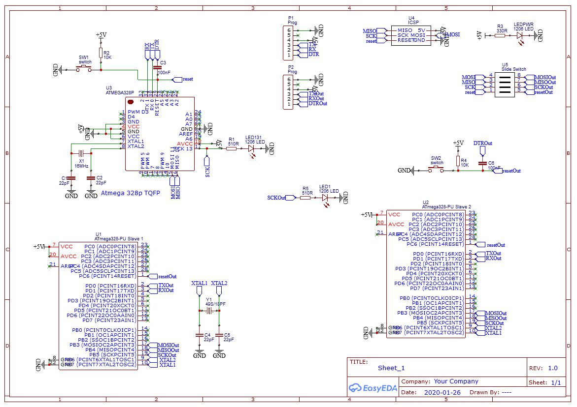
Here you can see the main MCU U3, which works as expected, I think. I can upload a sketch on it through the P1 header. There is a LED on pin 13 which can blink, etc. I don't think there is a problem with that part. U4 header is an ICSP header which I used to burn the bootloader on this Atmega328p.
U5 is a 4 DIP switch to disconnect SPI lines from the programming MCUs and SPIs from two sockets. When off, I can upload a sketch safely on this MCU.
The second part of a PCB is two sockets with shared components. I made it this way because I never intend to put two MCUs at the same time.
It looks ok on my PCB, but, not good enough.
When I upload the Atmega_board_detector on U3 with DIP OFF, it is ok. When I disconnect it and put DIP ON, to make U3 communicate with U1 or U2 serial shows that it can not enter programming mode. Which say or there is no MCU, or wiring is bad.
Funny thing is when I use the same Nano and connect its SPI by wires with SPI on DIP socket directly, I can program TQFP MCU on the second socket. With DIP switches off.
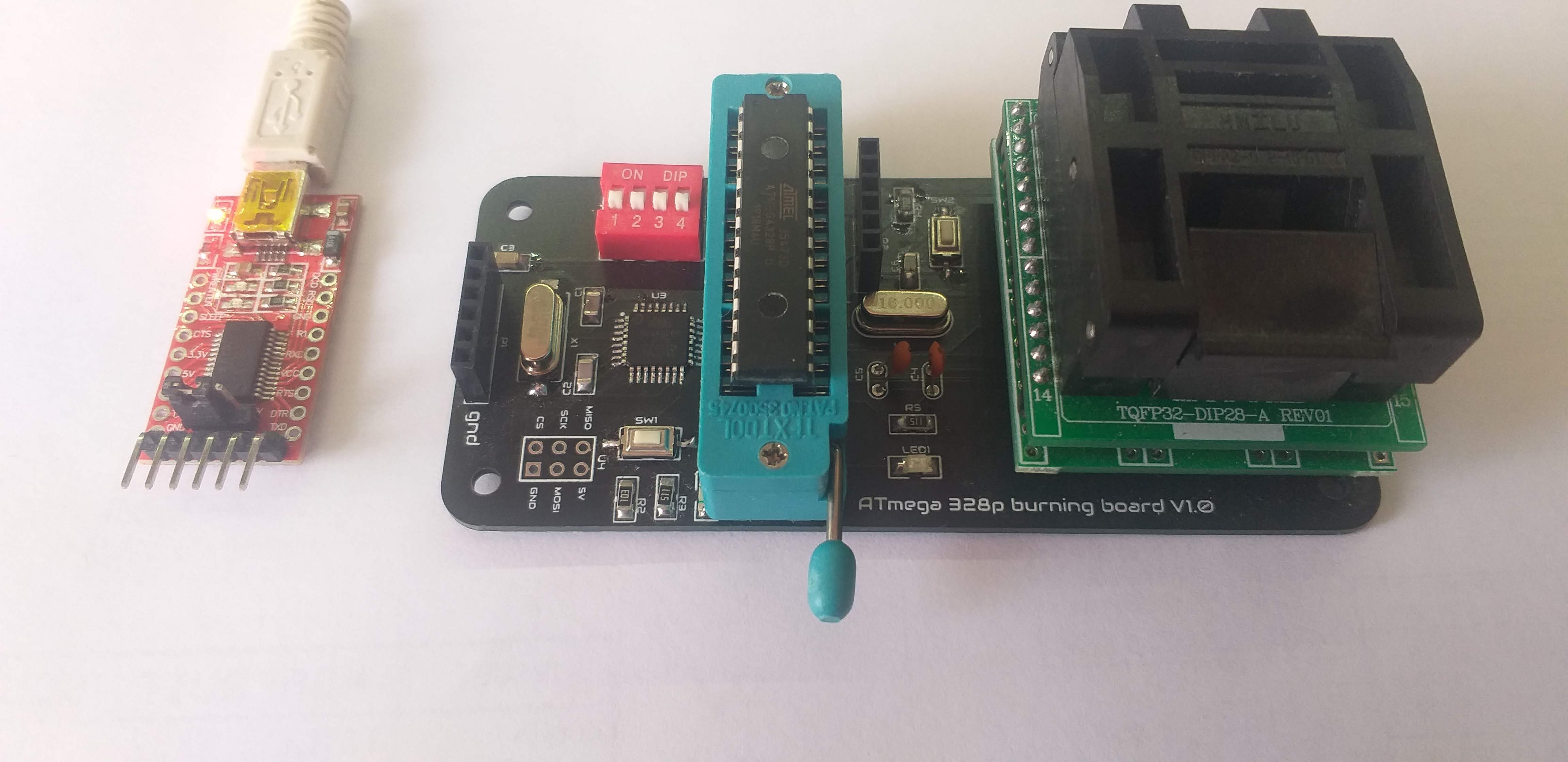
Here is the actual picture of the board.
I am sorry for the text wall. If need more info, please let me know.