Load cell power wires to E+ E- HX711
Load cell signal wires to A+ A- HX711
But it seems like the comment in the load cell picture is wrong. Most load cells has different wire colour scheme - Red and Black are power, Green and White - signal
Your topic has been moved to a more suitable location on the forum. Installation and Troubleshooting is not for advice on (nor for problems with) your project.
The load cell is a little unusual in it's color coded configuration but not the first I have seen like this. I have also seen Black Power + , white Power - Red Signal + green signal - so nothing surprises me anymore.
According to your posted sheet Black is E- (Excitation -), Green is S+ (Signal +), Red is S- (Signal -) and White is E+ (Excitation +)
So on your HX711 board E+ is White, E- is Black, A- is Red and A+ is Green.
This is a change from what was a sort of standard for decades but again I have seen the color schemes deviate on some imported load cells. I would start by connecting it based on your posted diagram.
A load cell like this simply consists of 4 resistors, and nothing in it is polarized, so the black and white excitation wires are interchangeable. In fact I think you could power it via the red and green wires and get the output from white and black just the same! But if the data sheet said black and white are for power, that's how I'd wire it.
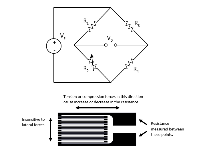
So we have a Wheatstone bridge where R2 is a Strain Gauge. If R1, R2 (strain gauge), R3 and R4 are all 350 Ohms, all equal in value the bridge output will be 0.0 VDC since the bridge is in a balanced state. However if the strain gauge resistance changes increasing ir decreasing the voltage out of the bridge will change positive or negative depending on what R2 does and the change will be directly related to how the Excitation is applied. Tension or compression so the polarity of the applied excition does matter and is important.
For my purpose where I only need to measure down force, I can in code change polarity of measurement, so in that case I can connect without thinking of polarity.
It's not just about the code. It's about a negative voltage with respect to zero volts going into the analog in pins of the uC (Arduino). That is not going to work very well since the Arduino is desinned for a positive input with respect to ground. The code has nothing to do with it.
But the bridge is not connected to the Arduino. It is connected to the HX711, which doesn't care about the polarity of the differential signal on A+ and A-.
In a load cell like that there are 4 strain gauges, printed the same way in order to get nearly identical resistances, and arranged on the bar above that slot so they are loaded complimentary, with a gauge in tension and another in compression on each half-bridge, and also so that the half bridges are complimentary, so if the voltage goes up on one signal wire, it goes down on the the other. It isn't polarized in the sense that the operation is non-linear like a diode or transistor and you must not load it backwards--it elements are all operating like linear resistors in bulk-resistance regime and it's all symmetric. If the polarity of the output isn't want you want, you can swap polarities of the excitation or sense terminals to switch the polarity of the output.
I agree as to the HX711 but it just seems to make more sense to connect things by the numbers rather than reverse excitation for a compression load cell. Yes the HX711 will accept a full-scale differential input voltage of ±20mV or ±40mV so an input below 0.0 volts but why not just connect it with the excitation + and - as the load cell data sheet?
This suggests a misunderstanding of bridge output.
The ±20mV or ±40mV are not relative to ground (0.0v): they're a differential between the A pins.
The HX711 common mode voltage is approximately 2.15v, half of the 4.3v excite. Measured against ground (E-) at full scale, one "A" pin may be 2.16v and the other 2.14v, for a differential of 20mV, (either positive or negative 20mV, depending on how you hook up your leads to both A pins).
Dave I understand that. My point is that why not just connect a load cell per the disgram or in this case the printed data. Connect the excitation positive and negative per the load cell pinout. Reversing the excitation will result in reversing the Sig + and Sig - load cell out. That in turn will change the sign on the HX711 output. For example if I apply 40 pounds of force to a compression load cell and read the data out I will get -40 rather than 40. I just figure, even using the HX711 that it's easier to connect things per the drawings than reverse anything. I see this as especially true in a load cell measuring both compression and tension where I like to see compression as a positive number and tension as a negative number. I am not saying reversing excitation voltage when using a HX711 won't work because it will. I am saying less a good reason to do it I would run with the load cell data as to excitation. I know the output is not relative to ground. That is sort of obvious looking at a bridge diagram.