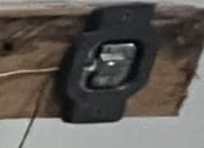
They look like three-wire half-bridge load cells with two strain-gauges per cell. If you carefully wire them up in a ring, you can have two strain gauges that constructively sum the strains in each leg of a wheatstone bridge between the half-bridge cell's center tap wire:
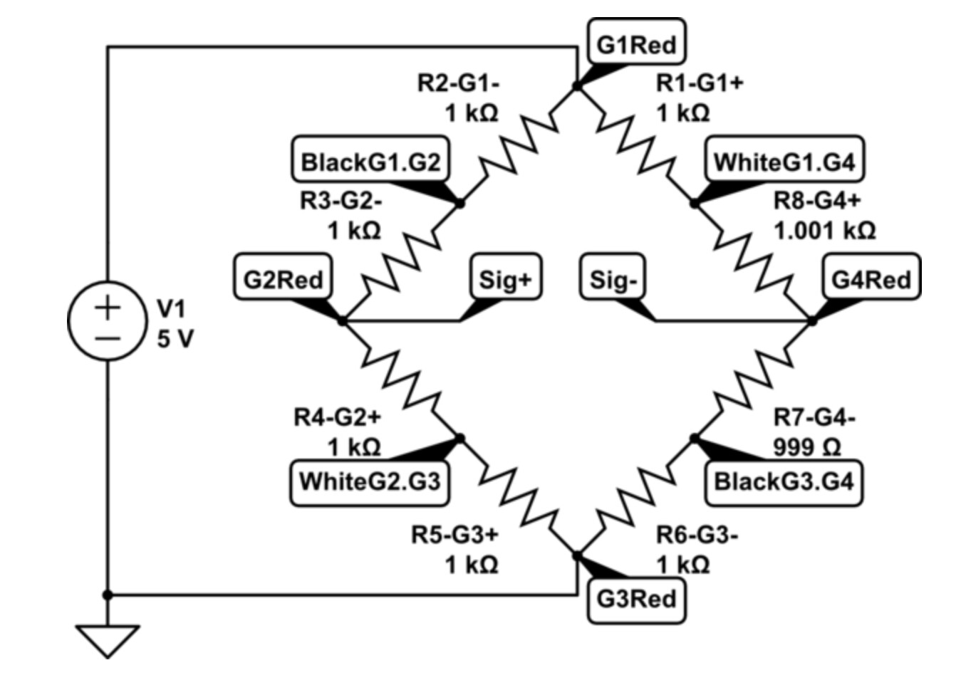
Where Gx represents half-bridge 'x', and nodes labeled like "WhiteG1.G4" represent the white leads from gauges 1 & 4. And the two resistors between the "BlackG1.G2", "G1Red" and "WhiteG1.G2" represent the two strain gauges in the G1-half-bridge. As per https://electronics.stackexchange.com/questions/102164/3-wire-load-cells-and-wheatstone-bridges-from-a-bathroom-scale/199470#199470
The resistances look OK as far as the 3-digit resolution goes, but the HX711 load cell amplifier needs much more precision. Each leg of the resultant Wheatstone bridge ends up with about 0.98K+0.98K=1.97K ohms in it, and the bridge needs to be balanced well within 0.020V/50V=0.4% or 2000*0.004=8 ohms. Instead of measurining kilo-ohms, try the millivolt range on your DMM and check that the A+/A- voltage is well within the +/-20mV range that the HX711 A channel needs so that "tare" will work properly.
Did you try the calibration sketch fron the library?