The problem is i connected the motors and pins as stated but no life from the motor controller. However when i connect it to a battery there is a mall spark where the wires and the battery connectors meet. (not sure if thats an issue or not)
I have used the library they provided and nothing happens
I have also used the code i wrote up based on the connectivity of the motor nothing happens.
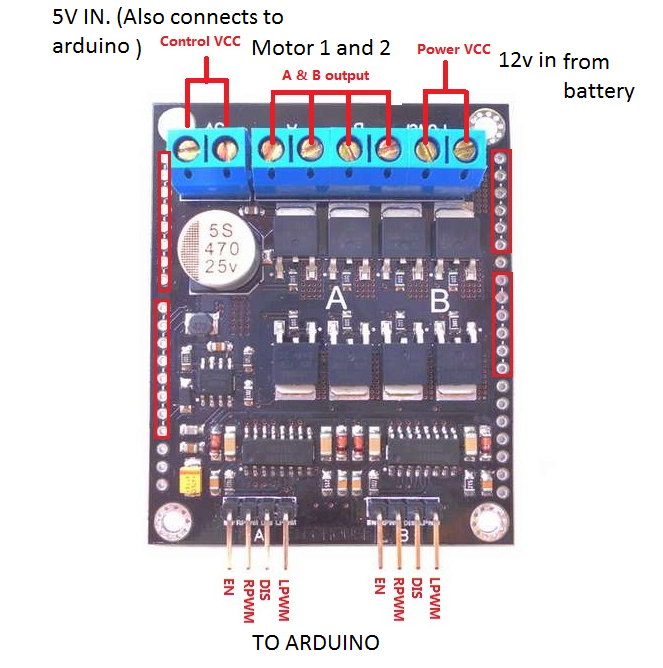
I have also tried connecting a 5v power source to the "Control VCC" terminal, and nothing. Here is my code.
Please help me. this motor controller also arrived weeks late and having to wait for a replacement will kill me.
/*ELECHOUSE 50A MOTOR CONTROLLER TEST CODE BY TAWANDAPRO*/


 int ENA=2;// enable for channel A
 int RPWMA =3;
 int LPWMA =5;
 int ENB = 8;//enable for channel B
 int RPWMB = 9;
 int LPWMB = 6;
void setup()
{
 pinMode(ENA,  OUTPUT);
 pinMode(RPWMA,OUTPUT);
 pinMode(LPWMA,OUTPUT);
 pinMode(ENB,  OUTPUT);
 pinMode(RPWMB,OUTPUT);
 pinMode(LPWMB,OUTPUT);

}


void loop()
{

  //RUN CHANNEL A MOTOR BY ITSELF
  digitalWrite(ENA,HIGH);// ENABLE CHANNEL A = HIGH
  analogWrite(RPWMA,255); //PWM SPEED =MAX
  digitalWrite(LPWMA,HIGH);//ROTATE FORWARD
  delay(3000);  // WAIT FOR 2 SECONDS


  //RUN CHANNEL B MOTOR BY ITSELF
  digitalWrite(ENB,HIGH);// ENABLE CHANNEL B = HIGH
  digitalWrite(RPWMB,HIGH);//ROTATE REVERSE
  analogWrite(LPWMB,255);//PWM SPEED = MAX
  delay(3000); //WAIT FOR 2 SECONDS

}
What connections do you have between the motor controller, Arduino, and battery?
What sort of battery is it?
A small spark when you connect the battery to the motor supply terminals of the board is nothing to worry about - it's probably caused by the decoupling capacitor charging. OTOH a large spark followed by smoke means you have connected the battery the wrong way round.
The spark you see when connecting the battery is probably becasue of the capacitor on the board being charged. if its so its nothing to worry about.
There is one litte issue though. If you read the tetxt on the website carefully it says(below the pinout table):
Please note:
Smaller PWM duty will get higher speed.
So change the PWM value into a smaller one and try again.
tawandapro:
I have a 5v power supply going to the arduino and the "Control VCC" to control the chip on the motor controller according to the the instructions
..and what ground and signal wire connections between the Arduino and the controller board?
Hi, it looks like we will need to see a circuit diagram of your setup, either cad diagram, or a hand drawn photographed schematic will be fine.
Please include how your supply is connected.
As a safety feature have you got a fuse in the main motor supply lead to the controller, 50A is a lot of current to work with.
Also have you a multimeter to check that the motor controller is getting the correct signals.
This will help us a great deal to suggest solutions to your problem.
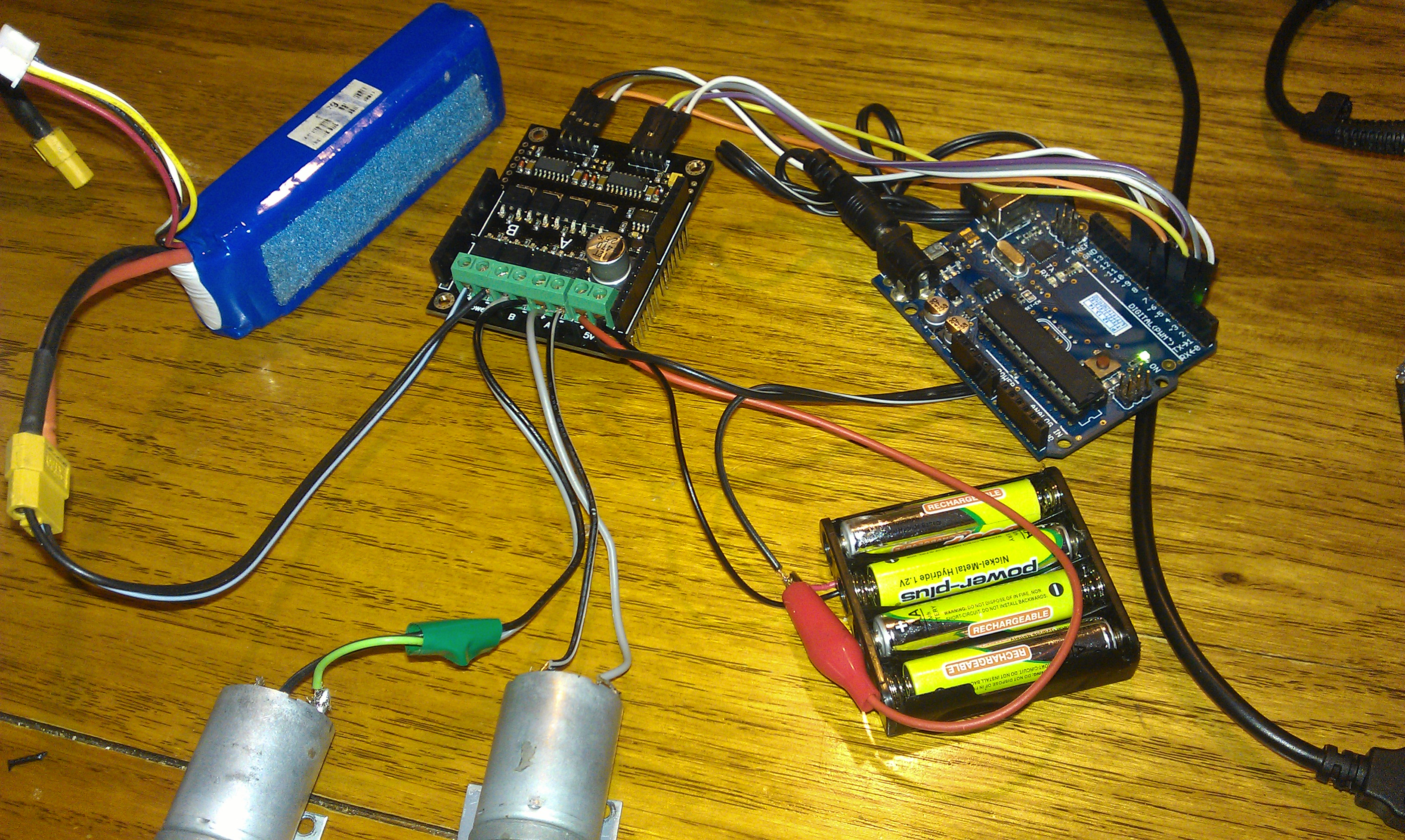
You appear to be feeding about 4.8V from the four NiMH cells into the Arduinio barrel jack. That will only provide the Arduino with a little over 3V, which may not be enough. I suggest instead that you connect the motor driver +5V and ground to Arduino +5V and ground, and power the Arduino either from USB or from 7V or more fed into the barrel jack.
You appear to be feeding about 4.8V from the four NiMH cells into the Arduinio barrel jack.
I have tried using a 5v 1.5 Amp voltage regulator to both the arduino and the motor controller. I will try again with a separate 6v supply for the arduino and connect the 5v regulator just to the motor controller and hook it up the grounds from the arduino, the regulator and the 12v power supply. The seller told me to share a 5v supply from the arduino to the motor controller.
Hi, have you checked with a multimeter that the appropriate input pins on the controller board are receiving the proper voltages when they are supposed to from the output of the arduino?
The code you posted will at the moment is, turn on the first motor and 3 seconds later turn on the second, then both will continue to run. You have not provided any commands to stop the motors, but at this stage that is not important as continuous running will make it easier to check output signals.
Hi, have you checked with a multimeter that the appropriate input pins on the controller board are receiving the proper voltages when they are supposed to from the output of the arduino?
yep that i did and there was 5v from the pins so the signal was being sent from the arduino.
I had one of these controllers. Mine was used in shield-form, and for only one motor. It lasted all of 2 months before it stopped working, so I guess I had a smidgin more luck than you. Asked for a refund or replacement, Elechouse said that they have never had any problems with their motor controllers. I am the only person in the universe to have had motor controller death.
They suggested it be sent back to them so they could check it out to see if I deserved a refund or not. So I sent it back to China but it was unable to be delivered to the address they gave me, according to the tracking on my parcel. And that was the end of matters. No more contact from Elechouse, no refund, no nothing.
If the h-bridge MOSFETs are all N type, then the PWM signal setup may be important. The h-bridge may need the type PWM described in the info if the h-bridge depends on an internal charge pump setup. If the PWM pin is just set high, the h-bridge may not work.
zoomkat:
If the h-bridge MOSFETs are all N type, then the PWM signal setup may be important. The h-bridge may need the type PWM described in the info if the h-bridge depends on an internal charge pump setup. If the PWM pin is just set high, the h-bridge may not work.
That's an excellent point. If the OP can read the part numbers on the 3 chips on the board and let us know what they are, we should be able to work out whether it will work with PWM=255 or only with lower values. However, the OP said in an earlier post that he tried with PWM set to 127, to no avail.