Output
And I'm following the circuit diagram given in post #53.
Output
And I'm following the circuit diagram given in post #53.
Ah. Ok. In that case, you need to change your pin definitions at the top of your code as they are setup for your original wiring. I think this is the change you need to make:
#include <ModbusMaster.h>
#include <SoftwareSerial.h>

const int RO_PIN = 8;
const int DI_PIN = 9;
const int RE_PIN = 7;
const int DE_PIN = 6;
Yes, i did this and got output as shown in my previous post #61
Ok. Let's work backwards and see what change we did that broke things.
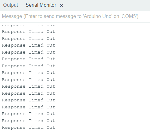
Firstly, remove the lines of code I suggested in post #60 and try the sketch again. That code shouldn't have caused the timeout message but you never know.
If that still produces the "Response Timed Out" message, then change the pin numbers back to:
const int RO_PIN = 10;
const int DI_PIN = 11;
const int RE_PIN = 8;
const int DE_PIN = 9;
And move just those 4 wires between the UNO and the RS485 module back to where they were.
Im getting mixed output now!

Updated code:
// Get ModbusMaster  at https://github.com/4-20ma/ModbusMaster

#include <ModbusMaster.h>
#include <SoftwareSerial.h>

const int RO_PIN = 10;
const int DI_PIN = 11;
const int RE_PIN = 8;
const int DE_PIN = 9;

SoftwareSerial swSerial(RO_PIN, DI_PIN); // Receive (data in) pin, Transmit (data out) pin
ModbusMaster node;

// Put the MAX485 into transmit mode
void preTransmission()
{
  digitalWrite(RE_PIN, 1);
  digitalWrite(DE_PIN, 1);
}

// Put the MAX485 into receive mode
void postTransmission()
{
  digitalWrite(RE_PIN, 0);
  digitalWrite(DE_PIN, 0);
}

void setup() {
  Serial.begin(9600);

  // configure the MAX485 RE & DE control signals and enable receive mode
  pinMode(RE_PIN, OUTPUT);
  pinMode(DE_PIN, OUTPUT);
  digitalWrite(DE_PIN, 0);
  digitalWrite(RE_PIN, 0);

  // Modbus communication runs at 9600 baud
  swSerial.begin(9600);

  // Modbus slave ID of NPK sensor is 1
  node.begin(1, swSerial);

  // Callbacks to allow us to set the RS485 Tx/Rx direction
  node.preTransmission(preTransmission);
  node.postTransmission(postTransmission);

  delay(1000);
}

void loop() {
  uint8_t result;
  // ask for 7x 16-bit words starting at register address 0x0000
  result = node.readHoldingRegisters( 0x0000, 7 );

  if (result == node.ku8MBSuccess)
  {
    Serial.print("Reply:: ");
    Serial.print(node.getResponseBuffer( 0 ));
    Serial.print(" ");
    Serial.print(node.getResponseBuffer( 1 ));
    Serial.print(" ");
    Serial.print(node.getResponseBuffer( 2 ));
    Serial.print(" ");
    Serial.print(node.getResponseBuffer( 3 ));
    Serial.print(" ");
    Serial.print(node.getResponseBuffer( 4 ));
    Serial.print(" ");
    Serial.print(node.getResponseBuffer( 5 ));
    Serial.print(" ");
    Serial.print(node.getResponseBuffer( 6 ));
    Serial.println("");
  } else {
    printModbusError( result );
  }
  delay(2000);
}

// print out the error received from the Modbus library
void printModbusError( uint8_t errNum )
{
  switch ( errNum ) {
    case node.ku8MBSuccess:
      Serial.println(F("Success"));
      break;
    case node.ku8MBIllegalFunction:
      Serial.println(F("Illegal Function Exception"));
      break;
    case node.ku8MBIllegalDataAddress:
      Serial.println(F("Illegal Data Address Exception"));
      break;
    case node.ku8MBIllegalDataValue:
      Serial.println(F("Illegal Data Value Exception"));
      break;
    case node.ku8MBSlaveDeviceFailure:
      Serial.println(F("Slave Device Failure"));
      break;
    case node.ku8MBInvalidSlaveID:
      Serial.println(F("Invalid Slave ID"));
      break;
    case node.ku8MBInvalidFunction:
      Serial.println(F("Invalid Function"));
      break;
    case node.ku8MBResponseTimedOut:
      Serial.println(F("Response Timed Out"));
      break;
    case node.ku8MBInvalidCRC:
      Serial.println(F("Invalid CRC"));
      break;
    default:
      Serial.println(F("Unknown Error"));
      break;
  }
}
In summary at this stage:
I wish we could monitor what was coming back from the sensor. I don't suppose you have an RS485-USB dongle?
It's not helped when the Modbus library is reporting 2 different errors. I might understand if it consistently reported "Invalid Slave ID" as we could possibly put that down to the rogue 00 we were seeing.
I don't have it right now, but I can get it from Amazon. somehow I need to fetch my sensor values on the serial monitor.
until yesterday it was reporting an "invalid slave id", but all of a sudden it changed to different, I wonder why!
Can you try the sketch from post #41 again. Make sure that your RE, DE, DI & RO are defined correctly.
We may have to put the proper Modbus library to one side till we can get the comms stable.
Don't worry about getting an RS485-USB dongle. We can probably figure it out without one.
now I don't see any output! RX doesn't give any values.

Is your 9V battery ok?
I am using it for a quite long time, I hope it's working!
I have two 9-volt batteries, when I tried to connect by combining 2 batteries, for a fraction of a second I got an output like this and went back to the previous state again.
At this point I would work on getting a suitable power source for your sensor. Do you have an old 12V power pack? Maybe one that powered a WiFi router - they are usually around 12V.
Note that an old laptop power pack may also work. I believe that they maybe around 19V, but check first.
Hi Mark, I have got a 12v DC power supply, and I'm using it now, the outputs are getting 00 now!
Code:
#include <SoftwareSerial.h>

const int RO_PIN = 10;
const int DI_PIN = 11;
const int RE_PIN = 8;
const int DE_PIN = 9;
const uint32_t TIMEOUT = 500UL;

// canned message to your RS485 device
uint8_t msg[] = {0x01, 0x03, 0x00, 0x00, 0x00, 0x07, 0x04, 0x08};

SoftwareSerial swSerial(RO_PIN, DI_PIN); // Receive (data in) pin, Transmit (data out) pin

void setup() {
  Serial.begin(9600);
  swSerial.begin(9600);
  pinMode(RE_PIN, OUTPUT);
  pinMode(DE_PIN, OUTPUT);
  digitalWrite(DE_PIN, LOW);
  digitalWrite(RE_PIN, LOW);
  delay(1000);
}

void loop() {
  uint32_t startTime = 0;

  Serial.print("TX: ");
  printHexMessage( msg, sizeof(msg) );

  // send the command
  digitalWrite(DE_PIN, HIGH);
  digitalWrite(RE_PIN, HIGH);
  delay( 10 );
  swSerial.write( msg, sizeof(msg) );
  swSerial.flush();
  digitalWrite(DE_PIN, LOW);
  digitalWrite(RE_PIN, LOW);

  Serial.print("RX: ");

  // read any data received and print it out
  startTime = millis();
  while ( millis() - startTime <= TIMEOUT ) {
    if (swSerial.available()) {
      printHexByte(swSerial.read());
    }
  }
  Serial.println();
  delay(2000);
}

void printHexMessage( uint8_t values[], uint8_t sz ) {
  for (uint8_t i = 0; i < sz; i++) {
    printHexByte( values[i] );
  }
  Serial.println();
}

void printHexByte(byte b)
{
  Serial.print((b >> 4) & 0xF, HEX);
  Serial.print(b & 0xF, HEX);
  Serial.print(' ');
}
output:
Your wiring should be like this to match the code you posted in #74:
Is your 12V DC power supply working?
There's no response from the sensor but you are still getting the rogue 00!
Are you using the same RS485 module that you showed in your first post - it looks just like the one in my image above.
Yes, I following this diagram but A is given to the yellow color wire of the sensor, and green is given for B as mentioned in the sensor manual. should I swap it and see it once?
yes, It's a new one I just got it, and it's working I checked.
Yes, it's the same RS485 module I'm using.
Still nothing ? Are you sure that sensor is working?
Btw, you don`t need separate pins for RE and DE, one is enough.
I don't understand, it's the new sensor I brought!
As long as A goes to A and B goes to B, the colours don't matter. You can swap them if you want to try it.
Still the same output! Is there any other way mark?


