Is that one of the rectangular 9V batteries that is really only for use in smoke alarms? I'm not sure that it has the capability to power your sensor.
Does your sensor operate from 5V? A lot of them seem to be in the 9V to 24V range.
Let's try something really basic just to see if your sensor is responding at all. The code below was written by myself to help other forum users with their NPK sensors. I've adjusted it to work with your current UNO wiring.
#include <SoftwareSerial.h>

const int RO_PIN = 10;
const int DI_PIN = 11;
const int RE_PIN = 8;
const int DE_PIN = 9;
const uint32_t TIMEOUT = 500UL;

// canned message to your RS485 device
uint8_t msg[] = {0x01, 0x03, 0x00, 0x00, 0x00, 0x07, 0x04, 0x08};

SoftwareSerial swSerial(RO_PIN, DI_PIN); // Receive (data in) pin, Transmit (data out) pin

void setup() {
  Serial.begin(9600);
  swSerial.begin(9600);
  pinMode(RE_PIN, OUTPUT);
  pinMode(DE_PIN, OUTPUT);
  digitalWrite(DE_PIN, LOW);
  digitalWrite(RE_PIN, LOW);
  delay(1000);
}

void loop() {
  uint32_t startTime = 0;

  Serial.print("TX: ");
  printHexMessage( msg, sizeof(msg) );

  // send the command
  digitalWrite(DE_PIN, HIGH);
  digitalWrite(RE_PIN, HIGH);
  delay( 10 );
  swSerial.write( msg, sizeof(msg) );
  swSerial.flush();
  digitalWrite(DE_PIN, LOW);
  digitalWrite(RE_PIN, LOW);

  Serial.print("RX: ");

  // read any data received and print it out
  startTime = millis();
  while ( millis() - startTime <= TIMEOUT ) {
    if (swSerial.available()) {
      printHexByte(swSerial.read());
    }
  }
  Serial.println();
  delay(2000);
}

void printHexMessage( uint8_t values[], uint8_t sz ) {
  for (uint8_t i = 0; i < sz; i++) {
    printHexByte( values[i] );
  }
  Serial.println();
}

void printHexByte(byte b)
{
  Serial.print((b >> 4) & 0xF, HEX);
  Serial.print(b & 0xF, HEX);
  Serial.print(' ');
}
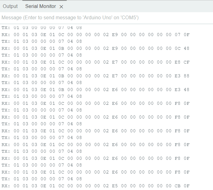
Note that the CRC16 checksum that you were using in your code was incorrect. The sensor should not respond to any message if the CRC16 checksum is wrong. I've put the correct checksum into my test piece of code for you.
If your sensor responds, then the RX line should display some numbers in hexadecimal - hopefully starting with 01 03.
Success! Your sensor is responding with what looks like the correct message.
You may be able to use that 9V battery but I don't know how long it will power your sensor for.
To get your code to work with the sensor, it looks like you need to correct the CRC16 checksum. That is the last 2 bytes in your command message byte array. The last 2 bytes should be 0x04 and 0x08.
Note that it would make your code a lot easier for you to write if you were to use the Arduino modbus library rather than trying to detect and decode the messages yourself. Let me know if you would like to try with the Modbus library and I will see if I can put together a simple demo for your sensor.
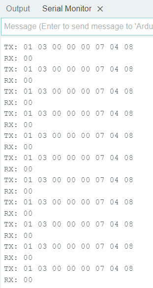
Strange. However, I just noticed that back in your post #42, the RX data starts with 00. That 00 shouldn't be there. The data should start with 01 (which is the slave ID). If your sensor is responding as it was for post #42, then the Modbus library will give you that error as it believes that the ID of the slave device responding is 00, when it is expecting 01.
Can you check your wiring - especially for a loose connection to the RE & DE pins.
Another thing you can try is to insert the following lines at the start of the loop:
void loop() {
  uint8_t result;

  // remove any characters from the receive buffer
  while ( swSerial.available() > 0 ) {
    swSerial.read();
  }
  // ask for 7x 16-bit words starting at register address 0x0000
  result = node.readHoldingRegisters( 0x0000, 7 );
One more thing is that it gives output only when I connect the positive terminal(Red wire) of my sensor to the 5v of Arduino Uno and the GND of the sensor (Black wire) to the GND of the Arduino UNO along with/ without battery if I remove these pins it gives maximum hexadecimal value FF FF FF FF FF so on. is it causes any concerns?
Your sensor probably won't function correctly when powered from the 5V output of the UNO as the label on the side of your sensor says it's a 7-24V supply.
You could try the 9V battery to power the sensor.
Also, check that you have wires that connect the UNO 0V to the RS485 GND and to the 9V battery -ve - i.e. a common ground.
Yes, I meant this, I have connected a 9v battery along with giving a positive terminal of the sensor(red wire) to 5v of UNO. the output comes 00 01 03 and so on only if I connect the red wire of the soil sensor to the 5v of uno with battery or without battery, if I remove the positive terminal(red wire) of my sensor to the 5V of UNO, The output gives a maximum hexadecimal value which is FF FF FF so on.
From your hand drawn wiring diagram, it looks like you have the 9v +ve connected to the 5v +ve. Disconnect the 5v wire from the UNO that goes to the 9v battery.
If it helps you out, here's a generic drawing I did some time ago on how to wire up an NPK sensor to an UNO via an RS485 module. The 4 pins used on the UNO will change depending on your own choices of pins.
hi mark, may I know the reason why all of a sudden it started showing 00? hope none of my devices got damaged! can you send me the simple code to check my devices, please?
It's difficult to say without the hardware in front of me. I don't know what damage may, or may not, have been caused by connecting your 9V battery + & - to the Arduino UNO 5V & GND. With a bit of luck, you may find that you didn't damage anything as those 9V batteries are pretty poor at providing power for anything that isn't a smoke alarm.
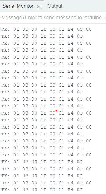
I do have some code that you can use to simply test that your UNO and RS485 board is working. It's a simple RS485 loopback test - but it has to use a software serial library called AltSoftSerial as that one can send and receive at the same time.
This is the code:
// This attempt uses the AltSoftSerial library & raw Modbus packets.
// It has been modified to put the MAX485 chip into loopback mode to
// check that the line driver & line receiver are working.
//
// RS485 module wired up as:
// RS485 DI signal to pin 9   <- It has to be this pin
// RS485 RO signal to pin 8   <- It has to be this pin
// RS485 RE signal to pin 6
// RS485 DE signal to pin 7
// RS485 VCC to 5V
// RS485 GND to GND
//
#include <AltSoftSerial.h>

#define RE 6
#define DE 7

const uint32_t TIMEOUT = 500UL;

// canned message to your RS485 device
// change this for any other canned modbus message you like
// remember to make sure that the checksum is correct!
uint8_t msg[] = {0x01, 0x03, 0x00, 0x1E, 0x00, 0x01, 0xE4, 0x0C};
uint8_t rxByte;

AltSoftSerial swSerial;

void setup() {
  Serial.begin(9600);
  swSerial.begin(4800);
  pinMode(RE, OUTPUT);
  pinMode(DE, OUTPUT);
  digitalWrite(DE, LOW);
  digitalWrite(RE, LOW);
  delay(1000);
}

void loop() {
  uint32_t startTime = 0;

  Serial.print("TX: ");
  printHexMessage( msg, sizeof(msg) );

  // send the command
  digitalWrite(DE, HIGH);
  digitalWrite(RE, LOW);    // keep the receiver enabled to hear our own transmission
  delay( 10 );
  swSerial.write( msg, sizeof(msg) );
  swSerial.flush();
  delay(100);
  digitalWrite(DE, LOW);
  digitalWrite(RE, LOW);

  Serial.print("RX: ");

  // read any data received and print it out
  startTime = millis();
  while ( millis() - startTime <= TIMEOUT ) {
    if (swSerial.available()) {
      printHexByte(swSerial.read());
    }
  }
  Serial.println();
  delay(2000);
}

void printHexMessage( uint8_t values[], uint8_t sz ) {
  for (uint8_t i = 0; i < sz; i++) {
    printHexByte( values[i] );
  }
  Serial.println();
}

void printHexByte(byte b)
{
  Serial.print((b >> 4) & 0xF, HEX);
  Serial.print(b & 0xF, HEX);
  Serial.print(' ');
}
You can change the RE & DE pins to suit your own setup, BUT the RO & DI signals must go to pins 8 & 9. That's a requirement of the AltSoftSerial library and the way it uses the hardware.
When you run the sketch, you should see it print out the TX message and then the RX message. If the RX message is the same as the TX message, then you have some confidence that your UNO and RS485 modules are working.
Yes, it's coming back what we are sent! still, I wonder why all of a sudden it started showing 00 in post #52. Since I connect 5V uno to my sensor, now my sensor at fault? because the NPK sensor ranges from 7-24V DC.
If you mean that you power your sensor from the UNO +5V, then that is likely to be an issue as your sensor requires at least 7V to function correctly.
The screenshot you have uploaded shows that stray 00 at the end of the received message. I'm not sure where that is coming from. The good thing, I suppose is that it is at the end of the message.
I suspect that the earlier code that reported back INVALID SLAVE ID was because the stray 00 was still in the receive buffer when the next transmission happened. The Modbus code likely then read in that stray 00 as the first byte of the response and would have generated that error message as it was expecting 01 as the slave ID.
I just had a look and there is a command that you can try - it should perform the same function as the bit of code I gave you back in post #48. Change your code by adding in this line:
void loop() {
  uint8_t result;

  swSerial.flushInput();     //   <-- add this line of code
  // ask for 7x 16-bit words starting at register address 0x0000
  result = node.readHoldingRegisters( 0x0000, 7 );

  if (result == node.ku8MBSuccess)
Oops. My fault! That function only exists in the AltSoftSerial library.
I'm wondering if the rogue 00 is generated when the RS485 module goes into TX mode. If you re-insert that bit of code I gave you so your loop starts with this:
void loop() {
  uint8_t result;
  // remove any characters from the receive buffer
  while ( swSerial.available() > 0 ) {
    swSerial.read();
  }
  // ask for 7x 16-bit words starting at register address 0x0000
  result = node.readHoldingRegisters( 0x0000, 7 );