DC motors are everywhere, from hobby applications to robotics and industrial areas. Therefore there is wide usage and request for suitable and powerful DC motor drivers. In this article, we will learn to build one. You can control it using a Microcontroller, an Arduino, a Raspberry Pi or even a standalone PWM generator chip. By using a proper heatsink and cooling methods, this circuit can handle currents up to 30A.

1: Circuit Analysis
The heart of the circuit is an IR2104 MOSFET driver chip 1. It is a popular and applicable MOSFET driver IC. The schematic diagram of the circuit demonstrated in figure-1.
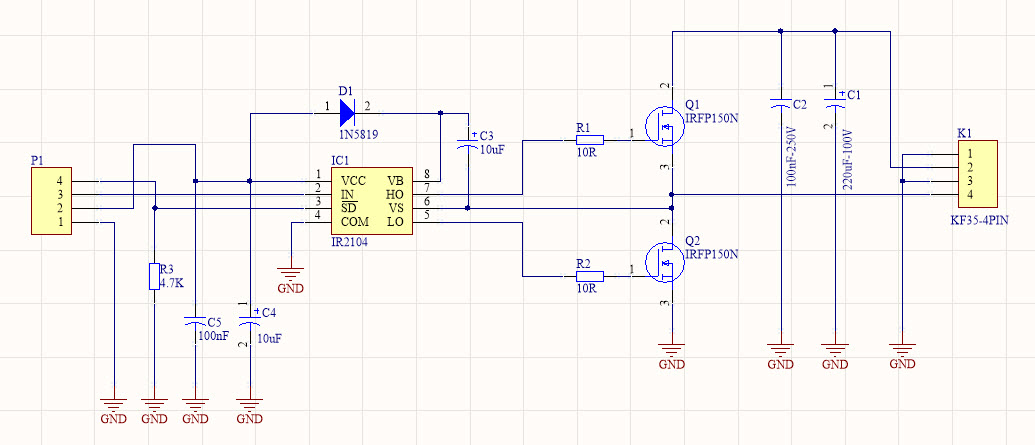
Figure-1, The schematic diagram of the powerful DC motor driver
According to the IR2104 datasheet 1: ”The IR2104(S) are high voltage, high-speed power MOSFET and IGBT drivers with dependent high and low side referenced output channels. Proprietary HVIC and latch immune CMOS technologies enable ruggedized monolithic construction. The logic input is compatible with standard CMOS or LSTTL output, down to 3.3V logic. The output drivers feature a high pulse current buffer stage designed for minimum driver cross-conduction. The floating channel can be used to drive an N-channel power MOSFET or IGBT in the high side configuration which operates from 10 to 600 volts.”
The IR2104 drives the MOSFETs 2 in a half-bridge configuration. There is no problem with the high input capacitance of the IRFP150 MOSFETs. That’s the reason why MOSFET drivers like IR2104 are useful. The capacitors C1 and C2 are used to reduce the motor’s noise and EMI. The maximum tolerable MOSFETs voltage is 100V. So I used 100V rated capacitors at least. If you are sure that your load voltage does not pass a threshold (for example a 12V DC motor), then you can decrease the voltages of the capacitors to 25V for instance and increase their capacitance values instead (for example 1000uF-25V).
The SD pin has pulled down with a 4.7K resistor. Then you must apply a steady state logic level voltage to this pin to activate the chip. You must inject your PWM pulse to the IN pin as well.
2: PCB Board
The PCB layout of the schematic demonstrated in figure-2. It is designed in a way to reduce the noise and transient to help the stability of the device.

Figure-2, Designed PCB layout for the motor driver schematic
I did not have the PCB footprint and schematic symbols of IR2104 1 and IRFP150 2 components. Therefore I use the SamacSys provided symbols 3 4, instead of wasting my time and designing the libraries from scratch. You can either use the “component search engine” or a CAD plugin. Because I used Altium Designer to draw the schematic and PCB, I directly used the SamacSys Altium plugin 5 (figure-3).
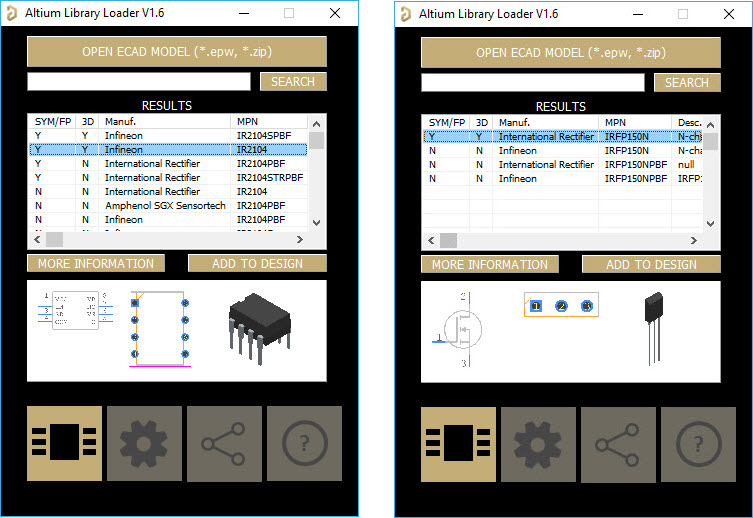
Figure-3, Selected component libraries for the IR2104 and IRFN150N
Figure-4 shows a 3D view of the PCB board. The 3D view improves the inspection procedure of the board and component placement.
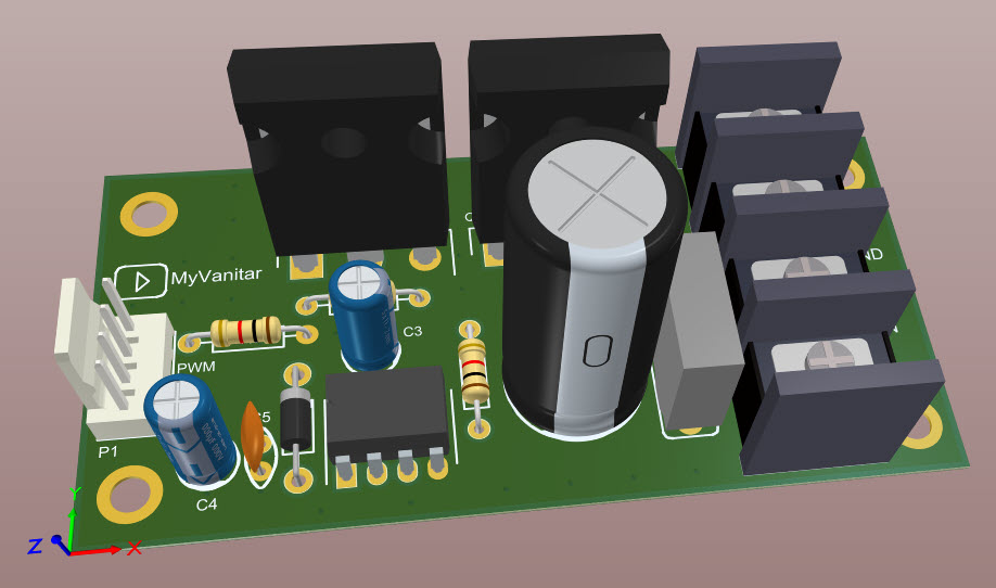
Figure-4, a 3D view of the motor driver PCB board
3 Assembly
So let’s construct and build the circuit. I just used a semi-homemade PCB board to be able to quickly assemble the board and test the circuit (figure-5).
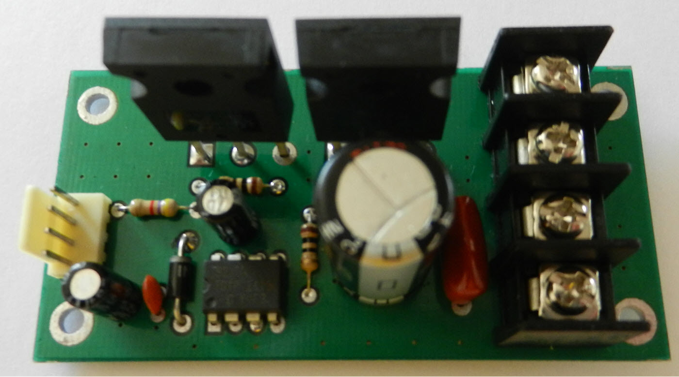
Figure-5, The first prototype of the design (on a semi-homemade PCB), Top view
After reading this article, you are 100% sure about the true operation of the circuit. Therefore order the PCB to a professional PCB fabrication company, such as PCBWay, and have fun with your soldering and assembled board [6].
Figure-6 shows a bottom view of the assembled PCB board. As you can see, some tracks have not covered completely with the solder-mask. The reason is that these tracks might carry a significant amount of current, so they need extra copper support.
A normal PCB track cannot tolerate a high amount of current and eventually, it will warm up and burn. To overcome this challenge (with a cheap method), you must solder a thick bare copper wire (figure-7) on the uncovered areas. This method enhances the current transmission capability of the track.

Figure-6, A bottom view of the PCB board prototype, the uncovered tracks

Figure-7, A thick bare copper wire
4 Test and Measurement
The provided YouTube video demonstrates an actual test of the board with a car’s windscreen wiper DC motor as a load. I have provided the PWM pulse with a function generator and examined the pulses on the motor wires. Also, the linear correlation of the load’s current consumption with the PWM duty cycle has demonstrated.
5 Bill of Materials
Table-1 shows the bill of materials.

Table-1, Bill of circuit materials
References