I got the 81 inch. I adjusted just using a screwdriver.
Right, the 1Amp version, and what voltage did you adjust the pot to.
And how did you measure it.
Vref (voltage on the pot) should have been adjusted to 0.8volt before the motor was connected.
Warning: Disconnecting/connecting the motor while powered will instantly destroy the driver.
Leo..
Isn't the pot adjusting the current limit? That was another issue, I was using multimeter on pot and GND. But the Vref was barely changing and was still very low. I did it a while back, so I'll update you on the exact values I get.
It should be rather low.
I calculated 800mV for 1Amp of motor coil current, with the 0.1 Ohm resistors on the driver you have.
Leo..
Those traces a way to thin to handle large currents.
Also you probably have several bad solder joints.
You need to do a redesign but for now redo all the losler joints.
Okay, then I can only warn everyone asking for help here about your tips. If the situations you describe in your post occur, something is fundamentally wrong. And then the real problem should be fixed. A heavily oversized power supply doesn't help; it only increases the risks.
No more responses to this problem from my side ( End of discussion ![]()
![]() )
)
Ah, I see didn't think about that. So, when I order do I need to set the trace width to be larger or would it be better to have it not connected through a PCB board? I also checked JLC PCB and 0.3mm with 2oz seems to be the max copper trace, will that be enough?
Yup, I was able to get it to 800mV. And as I adjusted the pot the mV changed accordingly, so its a good sign that the a4988 is fine.
Copper weight is done at ordering, trace width is done in your design program.
1oz is the default, but you can order boards in 2oz for extreme power cases, which this isn't.
You can make the traces as wide as you wish.
Only need to change the traces that carry significant current.
So driver supply and motor output.
See how wide you can make them without going too crazy.
A ground plane is something else you need to learn.
Leo..
You determine the trace width when you layout the board
Oh I see. Is this a likely issue though? Could I maybe test by using like some jumper cables to see whether it works then or not. Before reordering the board.
Was is the actual trace width of those motor traces.
A basic online trace width calculator told me that there is a temp rise of 50 degrees C with a 1A current through an 8mil trace. Four 8mil traces together makes that heating worse.
If a trace evaporates, it will kill the driver too.
To answer your question: it's not a problem until it is.
Leo..
Didn't know a trace could evaporate. I got a new stepper and gonna test my code and driver with an arduino uno. I'll update on how that goes.
Can you please post an image of the other side of your PCB?
You haven't answered if you have resoldered the joints I pointed out.
Thanks.. Tom.... ![]()
![]()
![]()
![]()
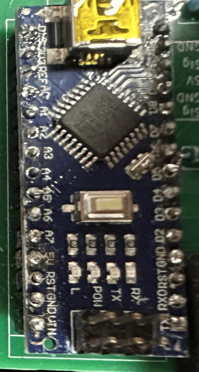


I see many bad solder joints there.
Watch a video, practise some soldering and redo all of them.
The biggest mistake beginners make is to put solder on the tip of the iron before soldering.
That burns off the flux inside the solder that you need for a shiny joint.
put the solder on the preheated pin/pad, not the tip of the iron.
Leo..
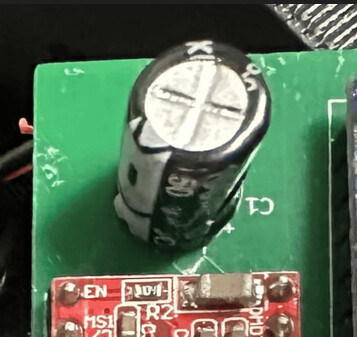
Hi, @kaipo1
Look at the electrolytic capacitor and where its negative marking is, it is not at the right angle when you look at the PCB pads.

These are just some that appear to be possible open circuits.
Not sure about the solder join between pins, is it supposed to be like that?
You need thicker tracks and thicker solder pads, to give you something to solder too.
Tom.... ![]()
![]()
![]()
![]()
I ordered and am awaitng a board with way thicker traces. However, I was thinking when I was using voltage regulator the amps would jump when I apllied mechanical load, wouldnt that mean that the trace is still there and that its properly connected to the stepper motor?