I've been working on this dog feeder project. I am facing an issue with my a4988 and stepper motor. I'm feeding motor 12V to VMOT and 5V(from arduino nano). I ruled out unstable power supply(measured and both were solid 12.02 and 5.02 and used variable DC power supply for the 12V), not the code as I used the same exact one as when I test built on breadboard(while also checking many times), the state pins are correct(checked many many times), moved the current limiter on driver around, and tested with spare driver.
I think the issue is either the amps cause the variable DC power supply was showing around 0.13 even when current limiter is on max. Or when I removed the female adapters of the stepper motor in order to solder to my board(in picture I have it straight to circuit board but I also tried putting tinned silver wire before) its an issue with that.
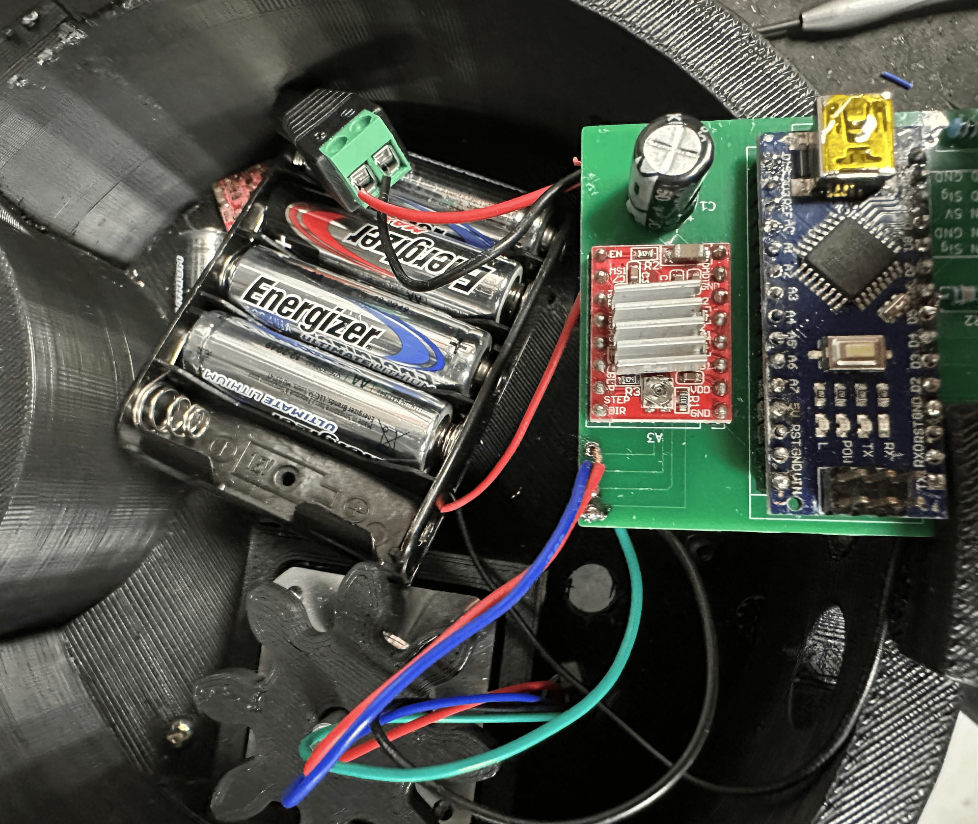
I got a photo of what I got below, but I've been working on this for a couple of weeks but can't figure it out. I was thinking about getting another stepper motor to test whether I need to keep the female adapter but want to make sure thats the issue before buying.
Let me know if you need any more specifics or better photos.
You need to set the driver current limit correctly, and for the A4988, that must be less than or equal to 1 Ampere/winding, and must not exceed the stepper motor winding current rating. Also, the motor power supply must be able to comfortably handle the total motor current.
Post a link to product page or data sheet for the stepper motor you are using.
Please post a link to the Motor datasheet. Not all steppers are suitable for the A4988. You need a low impedance stepper. Your stepper seems to be a high imedance stepper, but so far you did not tell us anything about your stepper.
No, it must comfortably be able to provide the power the stepper needs. With an A4988 and the appropriate motor, the current from the power supply is always significantly lower than the coil current of the motor.
Common practise is to adjust reference voltage on the pot with the pot before connecting the motor. Measuring motor or supply current is not a good way.
We still know nothing of your motor. Post a link.
The A4988 or the 12volt supply could be the wrong choices.
Leo..
Ok, this is a low impedance stepper. But it's rated current by far exceeds the limits of the A4988. And there must be something significantly wrong, if the PSU only shows 0.13A. 12V and 0.13A are only ~1,5W - far too low for this stepper.
NEMA 17 is the size of the mounting plate (1.7 inch). It tells us nothing about the electrical specs. The link you posted narrows it down to three models, which differ in hight.
But they all require (close to) 2A. 0.13A is far too low as @MicroBahner explained.
Which indicates that you did not set Aref properly. Pololu has good info for that. Your drivers seem to have 0.1 Ohm sense resistors.
Leo..
You cannot deactivate current limiting at an A4988. And that's true for all current controlling stepper drivers.
If there is no current limiting, you use a simple H-bridge.
Current limiting drivers do not limit coil current if the trip level is not reached.
There are a variety of errors, incorrect settings, pathological situations or system design mistakes, often found in amateur builds on a hobby forum, that can result in this condition.
My design philosophy is oriented more towards worst case situations, and generously over rating power supplies. End of discussion.
Now you're linking to a different family of six motors.
The first three motors in post#19 are a good match with the A4988,
the last three (thicker) motors could be needing a DRV8825.
Did you adjust the current pot on the driver, and HOW.
Leo..