this is a mega board
i want to be able to add up the binary position and store it in a variable to do things at certain counts
does the while add in the value when true and if not true then does not add in the value?
so far i have this but it just counts 100?
i can image how short a pro could code this but i like the long hand for ease of learning and viewing it.
                         //  encoder wires
int red    = 31;
int black  = 33;
int brown  = 35;
int orange = 37;
int yellow = 39;
int green  = 41;
int blue   = 43;
int purple = 45;
int gray   = 47;
int white  = 49;

volatile int degree;

void setup() {

  pinMode(red,    INPUT);
  pinMode(black,  INPUT);
  pinMode(brown,  INPUT);
  pinMode(orange, INPUT);
  pinMode(yellow, INPUT);
  pinMode(green,  INPUT);
  pinMode(blue,   INPUT);
  pinMode(purple, INPUT);
  pinMode(gray,   INPUT);
  pinMode(white,  INPUT);
  pinMode(LED_BUILTIN, OUTPUT);
  Serial.begin(9600);
}

void loop() {

  while  (digitalRead(red) == HIGH) {
    degree += 1;
  }

  while (digitalRead(black) == HIGH) {
    degree += 2;
  }

  while (digitalRead(brown) == HIGH) {
    degree += 4;
  }

  while (digitalRead(orange) == HIGH) {
    degree += 8;
  }

  while (digitalRead(yellow) == HIGH) {
    degree += 10;
  }

  while (digitalRead(green) == HIGH) {
    degree += 20;
  }

  while (digitalRead(blue) == HIGH) {
    degree += 40;
  }

  while (digitalRead(purple) == HIGH) {
    degree += 80;
  }

  while (digitalRead(gray) == HIGH) {
    degree += 100;
  }

  while (digitalRead(white) == HIGH) {
    degree += 200;
  }
  if (degree = 100) digitalWrite(LED_BUILTIN, HIGH);
  delay (100);
  digitalWrite(LED_BUILTIN, LOW);

  Serial.println (degree);

}
hmmmm, using the analog multi meter on the encoder i should be able to see a change between the ground and any of the output wires. i try them all at any position and get nothing. might be dead encoder?
turbothis:
hmmmm, using the analog multi meter on the encoder i should be able to see a change between the ground and any of the output wires. i try them all at any position and get nothing. might be dead encoder?
You have open collector outputs. Try the measurement after connecting a 4.7K pullup resistor from the encoder output to +5.
well i am pretty terrible at this so that might clear this up
i thought the while would be pretty straight forward as WHILE the condition is true then add in the amount to the total. and WHILE the condition is false then do not add in the amount
turbothis:
i thought the while would be pretty straight forward as WHILE the condition is true then add in the amount to the total. and WHILE the condition is false then do not add in the amount
That's exactly what will happen. Imagine the encoder is at position five ( binary 0101 ). WHILE bit zero is true the code will continually add a '1' to degree. It'll never get to add the four, or even check bit position 2.
i was afraid of that
is there an example some where on how to continuously add up things? or monitor the state
i swear every time i want to do something the only examples of i find are of LED codes wishing you happy birthday or flashing the star spangle banner in green blue and red. lol
turbothis:
is there an example some where on how to continuously add up things?
First, before checking the encoder bits set your accumulator to zero - to wipe the previous reading. Even better would be to do this in a separate 'scratchpad' variable then transfer the scratchpad to the working variable once all the relevant bits have been collected. Most important, change all the while()s to if()s.
Try this untested code.
It uses INPUT_PULLUP so active is LOW. The delay() when degrees == 100 will make the reading less responsive. How fast is the encoder turning?
int red    = 31;
int black  = 33;
int brown  = 35;
int orange = 37;
int yellow = 39;
int green  = 41;
int blue   = 43;
int purple = 45;
int gray   = 47;
int white  = 49;

int degrees = 0;
int previousDegrees = 0;

void setup() {
  pinMode(red,    INPUT_PULLUP);
  pinMode(black,  INPUT_PULLUP);
  pinMode(brown,  INPUT_PULLUP);
  pinMode(orange, INPUT_PULLUP);
  pinMode(yellow, INPUT_PULLUP);
  pinMode(green,  INPUT_PULLUP);
  pinMode(blue,   INPUT_PULLUP);
  pinMode(purple, INPUT_PULLUP);
  pinMode(gray,   INPUT_PULLUP);
  pinMode(white,  INPUT_PULLUP);
  pinMode(LED_BUILTIN, OUTPUT);
  Serial.begin(115200);
}

void loop() {
  degrees = readPosition();
  if (degrees != previousDegrees)
  {
    previousDegrees = degrees;
    //do something with the value
    Serial.println(degrees);
    if (degrees == 100)
    {
      digitalWrite(LED_BUILTIN, HIGH);
      delay (100);
      digitalWrite(LED_BUILTIN, LOW);
    }
  }
}

int readPosition()
{
  int position = 0;
  //!digitalRead() invert for INPUT_PULLUP
  position += !digitalRead(red);
  position += !digitalRead(black) * 2;
  position += !digitalRead(brown) * 4;
  position += !digitalRead(orange) * 8;
  position += !digitalRead(yellow) * 10;
  position += !digitalRead(green) * 20;
  position += !digitalRead(blue) * 40;
  position += !digitalRead(purple) * 80;
  position += !digitalRead(gray) * 100;
  position += !digitalRead(white) * 200;
  return position;
}
i put in the delay and led function to see something happen on the board
i run cattledog's code and still get nothing on the serial monitor or blinking LED on the board
i think i bought a dead used encoder
sucks they are 300$ new. lol
might get another used one......
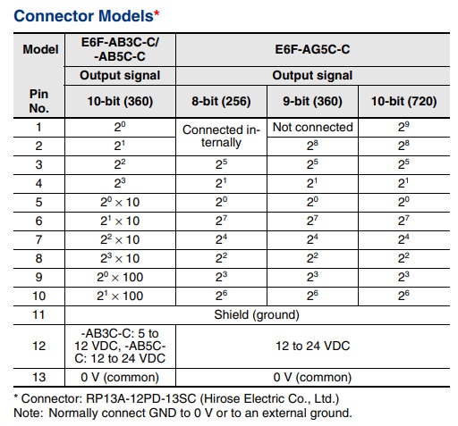
Your code shows wire colours that generally match the datasheet but you have red and black (power and ground) as inputs but no pink (2^0100) and light-blue (2^1100).
Without those two inputs you only have two BCD encodings and will have a count range from 0 to 99.
Is your wiring correct? If so, why are you confusing the matter with wrong color names?
Turn off INPUT_PULLUP. Substitute the encoder output for S2 so you have encoder output x to Arduino input *and *R1. Also, power the encoder separately, don't use UNO (assumed) power for that and don't use a supply greater than +5V. Connect the encoder ground to the Arduino ground. The same way the meter has to be connected to Arduino ground to take voltage readings, the encoder has to be connected to Arduino ground so they have a *common *reference.
Put your meter on the encoder/Arduino/R1 junction and test the voltage while turning the encoder slowly. If the voltage fluctuates work up a basic sketch to read the input and display it on the built-in LED or do a serial print of its status.
Your code shows wire colours that generally match the datasheet but you have red and black (power and ground) as inputs but no pink (2^0100) and light-blue (2^1100).
Without those two inputs you only have two BCD encodings and will have a count range from 0 to 99.
Is your wiring correct? If so, why are you confusing the matter with wrong color names?
The posted spec sheet for that encoder shows the colors and output values as the OP's code. For that model, the pink and light blue are ground and power.
cattledog: @turbothis show an image of an E6F-AB3C-C
The posted spec sheet for that encoder shows the colors and output values as the OP's code. For that model, the pink and light blue are ground and power.