I am replacing an EX100 PLC system with an Arduino Mega. The control voltage is 24VAC in the machine. There are 8 push buttons so can't use interrupts for each one.
I have used an ISR multiple times with a Common Interrupt Pin and array of pins for each push button. I want to use the following Push Button interrupt code:
void configure_Common (int common_Pin, int _arrayPins[], int _qnty)
{
pinMode (common_Pin, INPUT_PULLUP);
for (int i = 0; i < _qnty; i++) {
  pinMode (_arrayPins[i], OUTPUT);
  digitalWrite (_arrayPins[i], LOW);
}
void configure_Distinct (int common_Pin, int _arrayPins[], int _qnty)
{
pinMode (common_Pin, OUTPUT);
digitalWrite (common_Pin, LOW);
for (int i = 0; i < _qnty; i++) {
  pinMode (_arrayPins[i], OUTPUTINPUT_PULLUP);
}
}
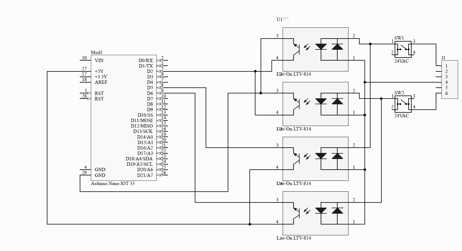
I was going to use 2 LTV814 optoisolator: PB Circuit.pdf (110.7 KB)
Due to space, I need to reduce to a single chip for each push button. I looked for a optoisolator triac that has AC input. Can't find any!! I know a triac only shuts off when current is low. I tried the circuit with a DC input and every time the code changes from Common to Distinctive, it shuts the triac off and works fine.
I was hoping someone can direct me to one or an alternative.
I am not sure what you are doing with your schematic. You can use one optocoupler and integrate the signal. The optocoupler on the schematic will detect AC, both phases. Add a capacitor to the output of th coupler ie. the input to the Arduino. Not sure what the pull up is but if it is the Arduino it will change from pin to pin and processor to processor. This will give you an input if a button is pushed. You can pole or use the pin change interrupt.
Thank you very much. I read over the SSR information and realized it was a simple solution. I put a 1N4007 diode in parallel to the MOC3023 LED, after the resistor.
The MOC3023 triac works great. Just like a PC814 optoisolator with a triac output.
Hi,
yes you can, it is possible to use interrupt for all arduino pins.
See this example para o UNO:
// Pin change interrupt for any pin

//-----------------------------
void pciSetup(byte pin)
{
  *digitalPinToPCMSK(pin) |= bit (digitalPinToPCMSKbit(pin));   // enable pin
  PCIFR  |= bit (digitalPinToPCICRbit(pin));                    // clear any outstanding interrupt
  PCICR  |= bit (digitalPinToPCICRbit(pin));                    // enable interrupt for the group
}
//----------------------------- // Use one Routine to handle each group
ISR (PCINT0_vect)               // handle pin change interrupt for D8 to D13 here
{
  digitalWrite(13, digitalRead(8) and digitalRead(9));
}
//-----------------------------
ISR (PCINT1_vect)               // handle pin change interrupt for A0 to A5 here
{
  digitalWrite(13, digitalRead(A0));
}
//-----------------------------
ISR (PCINT2_vect)               // handle pin change interrupt for D0 to D7 here
{
  digitalWrite(13, digitalRead(7));
}
//-----------------------------
void setup()
{
  int i;
  for (i = 0; i <= 12; i++)       // set pullups, if necessary
    digitalWrite(i, HIGH);        // pinMode( ,INPUT) is default

  for (i = A0; i <= A5; i++)
    digitalWrite(i, HIGH);

  pinMode(13, OUTPUT);            // LED

  pciSetup(7);                    // enable interrupt for pin...
  pciSetup(8);
  pciSetup(9);
  pciSetup(A0);
}
//-----------------------------
void loop()
{ }
I guess Mega has Pin Change Interrupt as Uno does. This can cause interrupt from any pin.
Anyway using interrupt for push buttons is usually not needed.