I have an Arduino Portenta C33 mounted on an Arduino HAT Carrier. How do I access the pins on the 40 pin connector from the Arduino IDE 2.3.x??? What pin designations do I need to use? Is there another header file and/or library I need to use to access the pins on the HAT Carrier 40 pin connector?
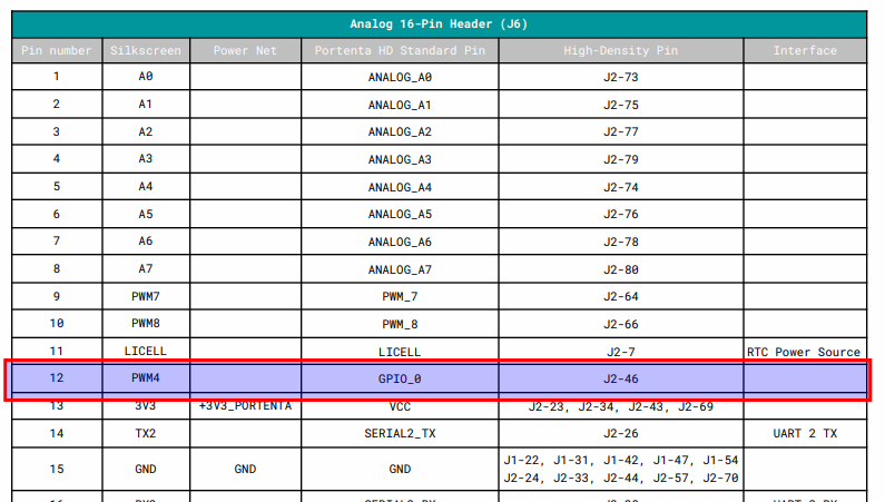
Yeah, well, jcarolinares, those drawings are CLOSE to being correct. However, for example, the Analog 16-pin Header (J6) has a pin called "PWM4" (at position 12) that is NOT connected as listed, but, instead, is hooked up to "GPIO_0" at IO #27! There are other errors in that document that need to be updated.
You can see that the first column is named "Silkscreen". As you probably know, the silkscreen is the text that you can find on the board itself. The idea of that column is to give the user the exact name that will find on the board with the idea of making easier the prototyping phase.
So in this case J6 Pin 12 is named as PWM4 on the board and internally connected to the Portenta Standard connector High-Density Pin GPIO_0.
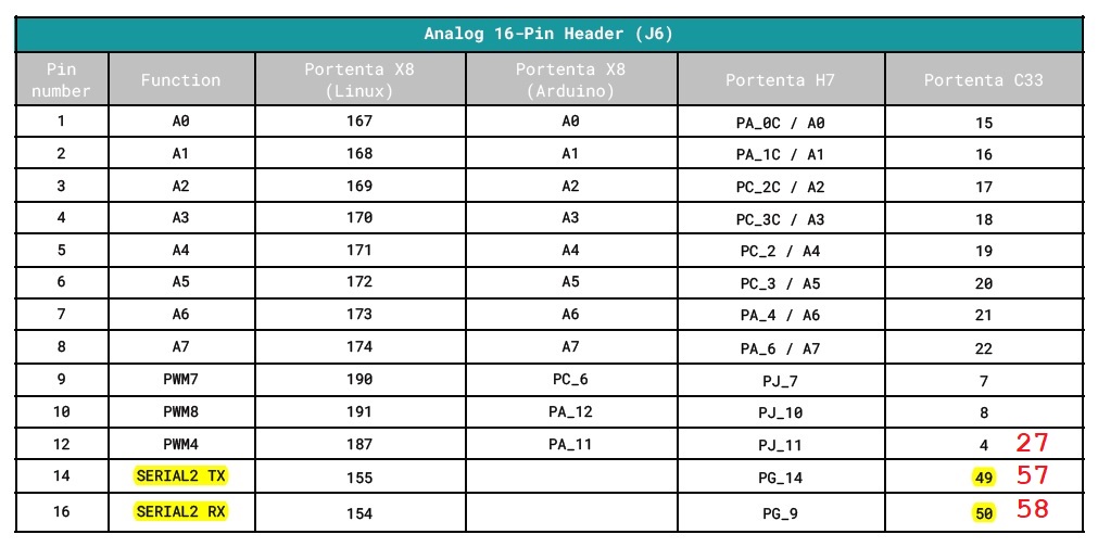
Now if you go to page 6 you can find how that pin has to be named inside your program depending on the board attached to your hat carrier:
So J6 Pin 12 is internally a GPIO that has been assigned via software to have the purpose of a PWM4, which is the assigned standard Portenta Connector Feature but depending on the board connected that function can differ.
Depending on the board connected to your hat carrier you will need to call it in your program:
Well, Jcarolinares, you have illustrated the ERROR accurately in your second image, and in your final text you have made a big mistake. You show, in that second image, and you wrote:
"Depending on the board connected to your hat carrier you will need to call it in your program:"
...
" * Portenta C33: 4"
This is COMPLETELY WRONG. In fact what is silkscreened on the Hat Carrier board on the Analog Header at "J6", pin 12, as "PWM4" is NOT ACCESSED as "4" in "your program", like you said, that pin is accessed, instead, as "27"!
So please update that pin-out document to reflect the correct pin "27" as IO "PWM4" on "J6".
Well, jcarolinares, I am so sorry to say but you are incorrect. That "PWM4" pin at J6 pin 12 (on the Hat Carrier Board) is accessed in "your program" as #27 and not as #4 as you have incorrectly indicated.
Let us take a look at the potential errors you are pointing out, as you can imagine these carriers have a high level of complexity, and making this kind of table where the number of variables is huge can lead to potential errors even with people double-checking.
We did a technical double-check regarding the problems you pointed out and fixed some of the issues you pointed out plus some additional ones. Thank you for your feedback.
To make it shorter you will find the updated document at: