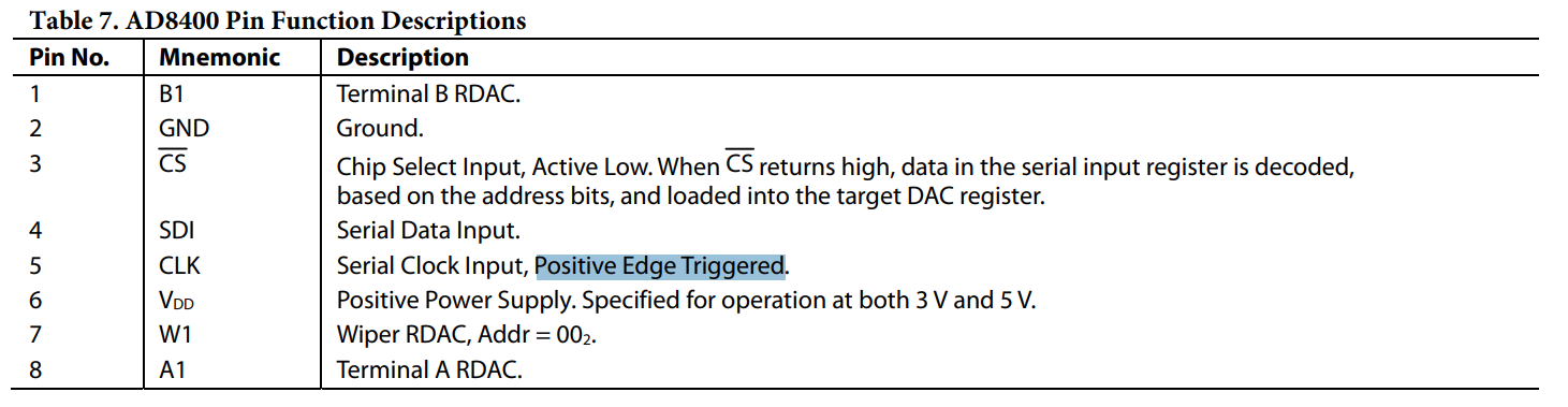
I am controlling the AD8400(1 kohm) digipot with Arduino Uno R3 using SPI interface. My connections are as follows:
Digipot <-> Arduino
CS(3) <->10
SDI(4) <-> 11
CLK(5) <->13
VDD(6) <-> 5v
GND <-> GND
I am checking the resistance across terminal W and B using multimeter after giving input between 0 to 255.But the resistance obtained is not varying linearly and it also exceeds the Resistor Nonlinearity((-4) -(+4) LSB) provided in datasheet.
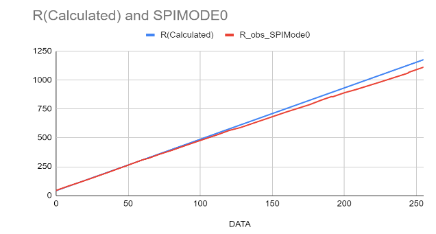
Below is the graph obtained for values between 0-255
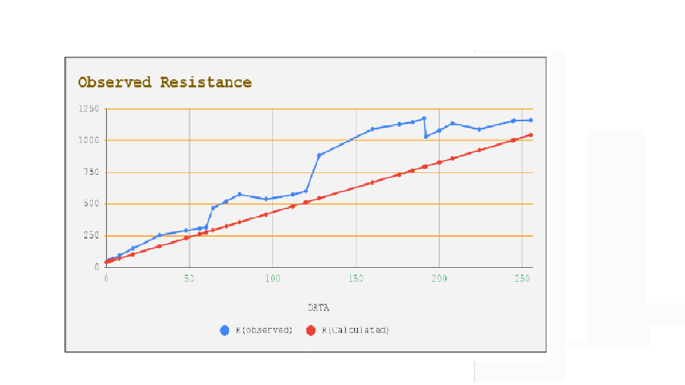
Blue line indicates the observed values
Red line is for the equation:
Resistance = 43.2 + (Data/ 255) * (1000)
Below is the code used:
#include <SPI.h> // include the SPI library
#define slaveSelectPin 10 // set pin 10 as the slave select for the digital pot
int address = 0; //addr bits = 0)
int value = 72; // value can be anything between 0 to 255
void setup() {
pinMode(slaveSelectPin, OUTPUT);// set the slaveSelectPin as an output:
Serial.begin(115200);
SPI.begin(); // initialize SPI:
}
void DigitalPotWrite(int addr, int val){
digitalWrite(slaveSelectPin, LOW);
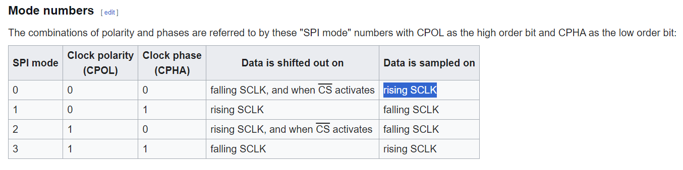
SPI.beginTransaction(SPISettings(10000000, MSBFIRST, SPI_MODE1)); //initialises SPI clock speed, mode and bit order
digitalWrite(slaveSelectPin, LOW);
SPI.transfer(addr);
SPI.transfer(val);
digitalWrite(slaveSelectPin, HIGH);
SPI.endTransaction();
}
void loop() {
digitalWrite(slaveSelectPin, HIGH); // ensure default CS stays high for now
DigitalPotWrite(address, value);
delay(5000); //arbitrary delay
}
Can someone please check what could be the error and how to reduce it??