I'm having trouble shrinking a project of mine from Arduino Uno to an Adafruit Pro Trinket 12V.
I just want to control a Relais and some status LEDs.
And yet it seems like the digital out signals do not supply enough power to run the circuit properly.
In fact, the Relais does not work anymore at all and the LEDs are much darker, just barely noticable.
I'm powering the trinket via an external 12V, 3A power supply connected to the "Battery" Pin.
If I use an external 5V power supply to simulate the signal output (istead of the trinket), everything in the circuit works fine. The displayed current never goes above 8mA.
I measured the voltage of the Adafruit trinket outputs to be close to the expected 5V. Maximum current I measured was around 100 mA, as expected from the datasheet. So this shouldnt be a problem in the first place.....
What am I missing folks?
In the IDE the adafruit package only contains the Trinket 5V, which I select for compiling and uploading the sketch, this cannot have something to do with it right?
Thanks so much in advance for any advice.
Best regards
Quote:"And yet it seems like the digital out signals do not supply enough power to run the circuit properly.
In fact, the Relais does not work anymore at all and the LEDs are much darker, just barely noticable.".
Do not ever confuse "signals" with "power"!!! Signals are for controlling something. Power is for powering something. Your Arduino is made to control something. Yes, it can power something like a LED with a series resistor to limit the current, but a signal cannot power much else.
Please show a schematic of your project and perhaps we can help solve the problem.
With "powering the circuit" I of course meant activating the relais which in turn sends the current to the actual circuit components.
The Relais activation should not take that much power (i assumed).
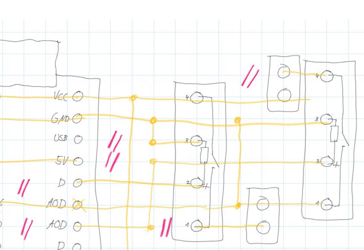
I attached an image of the circuit (circles are actual solders to the circuit board). I did only do the displayed part of the circuit yet, the connections running out of the image shouldnt have any impact.
Additionally I tried to power the circuit with 6V, with the same results.
Looks like you're trying to source coil current from D and A0D.
The Trinket can't output too much current on the IO pins. I'd suggest adding a current buffer.
I would connect one end of the coil to the + supply (5V, 12V, whatever they need) and use a simple NPN transistor to sink current thru the coil. IO pin to a 150 ohm resistor to the NPN base, NPN emitter to Gnd, and NPN collector to the coil.
Add a diode from the collecter side of the coil to the supply; anode on the collector side, cathode to the supply side.
Which Relay are you using - data sheet, or part number would be great.
I guess you're right. I was trying to avoid another "layer" of transistors.
Right now I'm using this Relais:
But if I have to use a transistor anyway, can't I just replace the relais completely by one transistor each?
(assuming I find the proper voltage configuration)
Do I still need protection diodes if there are no more coils but only transistors involved?
That relay (assuming you are using the 5V coil variant) has a coil resistance of 500R, which would mean a current of only 10mA and no need for a transistor. It may also have a protection diode built in. What is the exact model number printed on the relay?
Using a transistor instead of the relay depends on what you are switching with the relay. You mentioned "valves" earlier but gave no detail. I would think a logic-level n-channel mosfet could replace the relay, such as stp16nf06l or similar. But need more details to be sure.
Right now, I can't understand why your circuit is not working with the relay.
Ok sorry I thought I could spare you some details, but let me summarize my project:
An Adafruit Pro Trinket 5V shall control two Water-valves (12V 0.5A).
Due to the signal ports being way too weak to power something this big and relais seemingly not working as intended, I now want to try NPN transistors like this: https://www.reichelt.de/bipolartransistor-npn-20v-1a-0-8w-to-92-bc-368-p4992.html?&nbc=1
They are capable of 20V, 1A. That should work right?
No, with npn.transistors, you must have a resistor for the base pin to limit the current, otherwise the transistor or Arduino pin will be damaged. 220R should be ok.
Sooooooo
I made a small circuit to break down my problem (see sketch below).
Still not working.
I feel like I lack some minor understanding of transistors themselves but I just cannot figure out what I am missing.
By the way: The valve operates at 12V and requires about 0.15A while active.
I use the transistor BC368 in case that matters: Datasheet
Any other ideas?
Getting a little frustrated, but not yet willing to give up
One thing missing from your diagram is a "flyback" diode. There may be such a diode fitted internally to the valve, but unless you are 100% certain of that, you should assume there is not and add one yourself. Without this diode, the transistor can be damaged by negative voltage from the valve's coil when it is deactivated. 1N4001 should be OK, connected across the valve terminals, cathode to 12V.
Once you have fitted the diode, try disconnecting the 220R from Dout and connect it to 5V.
Update: Partial success here.
Using a flyback diode (thanks for the hint!) the circuit I posted earlier now works but only if I connect the transistor base directly to the 5V output.
Does not work with signal pins as intended.
How can I get them to work?
Already tried several resistor sizes, I dont have more than 10k here though. Would it help to increase the resistor even further?
I'm sorry I said it wrong. I did not connect the 5V directly to the transistor. I did use the 220R in between.
I will try some other pins this evening and report back
Thanks so far for you time everyone!