Hi There, I am using an Arduino Portenta H7 to sample analog signals. Currently, I am testing with two piezoelectric sensors, but I need to use eight. I require very high sampling frequencies, around 400 kHz. These frequencies can be easily achieved using the <Arduino_AdvanceAnalog.h> library. This library allows leveraging the DMP and reaching very high sampling speeds.
The problem is that when using two pins that are read by the same ADC (there are three ADCs), the pins interfere with each other in the measurements. However, if I use two different ADCs, meaning one for each pin, I do not encounter any issues.
I need to be able to use multiple pins on a single ADC and read them sequentially because I have eight sensors to connect, not just two. I have read that the issue might be hardware-related due to improper resistor usage since the capacitor in the ADC’s Sample & Hold system is charged too slowly.
I have used the same sensors and the same configuration as a research paper published online. Can anyone tell me if the problem could be the incorrect resistors used, or if it is something else? Unfortunately, I am a mechanical engineering student and do not have much knowledge of electronics, but I need this for my thesis.
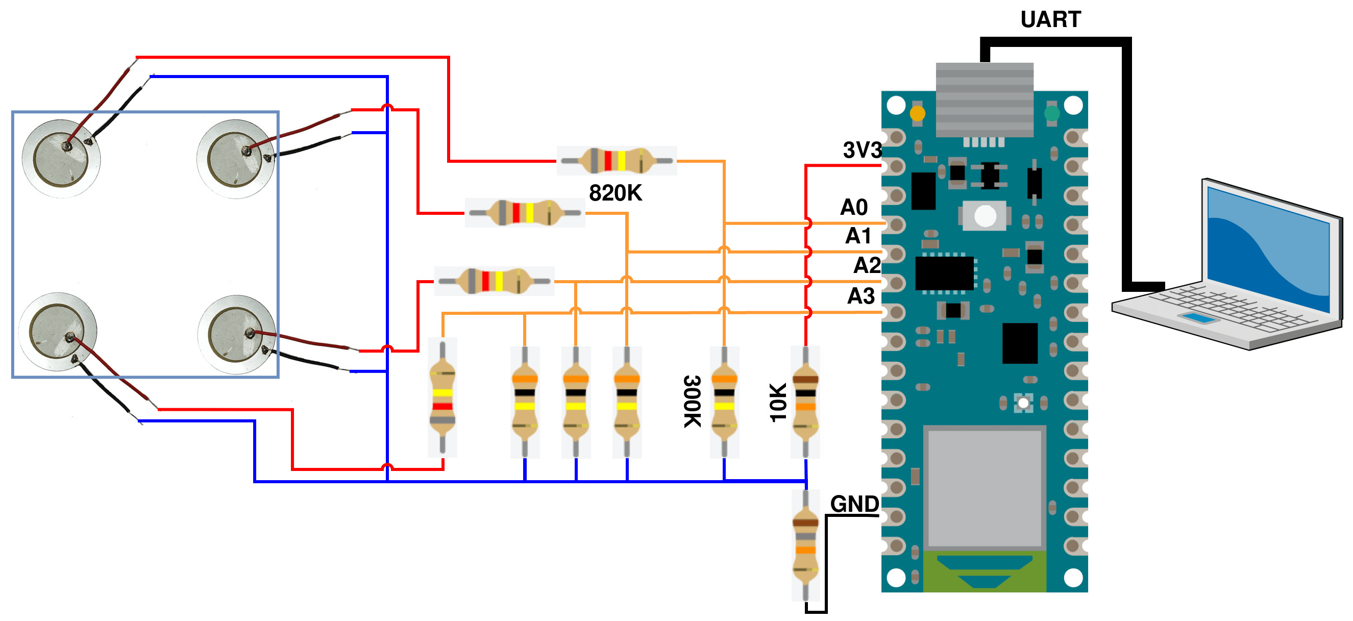
I am attaching a photo of the wiring diagram I used. Thanks in advance!
Those resistors ar pretty big. So filling the capacitor takes time. And your sampling rate may be faster than that time...
Smaller resistors may help. But piezo sensors are also high impedance...
A buffer opamp may provide a solution (one per piezo). Some opamps come with 4 pin one IC (quad opamp). That could make things easier...
You could try to calculate the time that is needed to fill the capacitors... but I cannot find the value of those capacitors...
Thank you very much! I'll study the use of the buffer opamp since it's the first time that I hear it. I'll also try to decrease the resistors. Another move that I've tried as debugger is to decrease the sampling rate untill 1kHz and the problem was still there. At 1kHz I've found the solution putting a very big resistor (2.2M) between the Analog pins and GND.
Processor used in Portenta (or close relative) https://www.st.com/resource/en/datasheet/stm32h747ag.pdf
Page 185 shows the impedance of the device driving the input to the A to D converter. Range is from 170 Ohms to 26500 Ohms, so way lower than you have. A buffer is essential for proper operation.
I think the note (6) implies that if you want a certain accuracy, you need to take that impedance into account. And that value should (in my opinion) also depend on the sampling rate.
It also says the input holding capacitor is 4pF.
That is pretty low... anyway, we know the resistors from op ant the capacitance, so we could calculate the time it will take for the voltage to settle to a certain accuracy. I will need paper and pencil to do so. Not the right moment now.
My gut feeling is that 4pF has little influence (at 200 kHz).
These values are usual in 100MHz devices...
But here we want to settle to 14 bit accuracy. That is also very little. So we need to do the math...
Thank you Perry! I didn't think about the STM datasheet, I referenced only on the Portenta ones. There are a lot of info that can be useful! Do you suggest any specific buffer opamp in particular?
Thank you again! I'll do the calculations when I can. The accuracy is important but I'll elaborate the signal for the training of a neural network. The step to have at least every measure independent from the previous is the most important.
Hi,
A possible quick solution, used in the the AVR chips coding.
If you have two inputs multiplexed to the same ADC, read the input twice each time you do an analogRead, this usually gives the ADC capacitor time to change from one channel to the other and get a reliable reading;
It's a long time since I needed an Op-amp. I have a box of TL071s, so if I were doing this I'd use those (or TL072, which has 2 in each package). You need a high input impedance, the TL071 etc has JFET inputs so it probably going to be OK. Otherwise search for one with MOSFET inputs.
Thank you for your Idea. The problem is that I'm using an advanced library for the Analog reading. I think that I can't select specifically how to read the inputs using the same ADC. If I use the same ADC for A0 and A1, it reads one at time. I can check if there's a way to do that. I'm using this library because with analogread I was able to achive only 90kHz per channel.
Hi,
If A0 and A1 are hardwire connected to the same ADC in the IC , then no matter what library you use they are read by the same ADC.
You best method might be to read in the data in to an array from the first sensor, then read in data from the second sensor into another array and compare them.
That way you are keeping the data acquisition time to ADC reads and not reads and input changing each sample.
could you share a link to that please? and also to the exact sensor you are using?
Also it would help us if you explained what you are trying to do.
Making sense of the output from a piezo sensor is not trivial. This provides a good explanation - and note
" Typically, the high impedance of the sensor requires an amplifier with high-input impedance. JFET or CMOS input op amps, like the TLV2771, are natural choices."
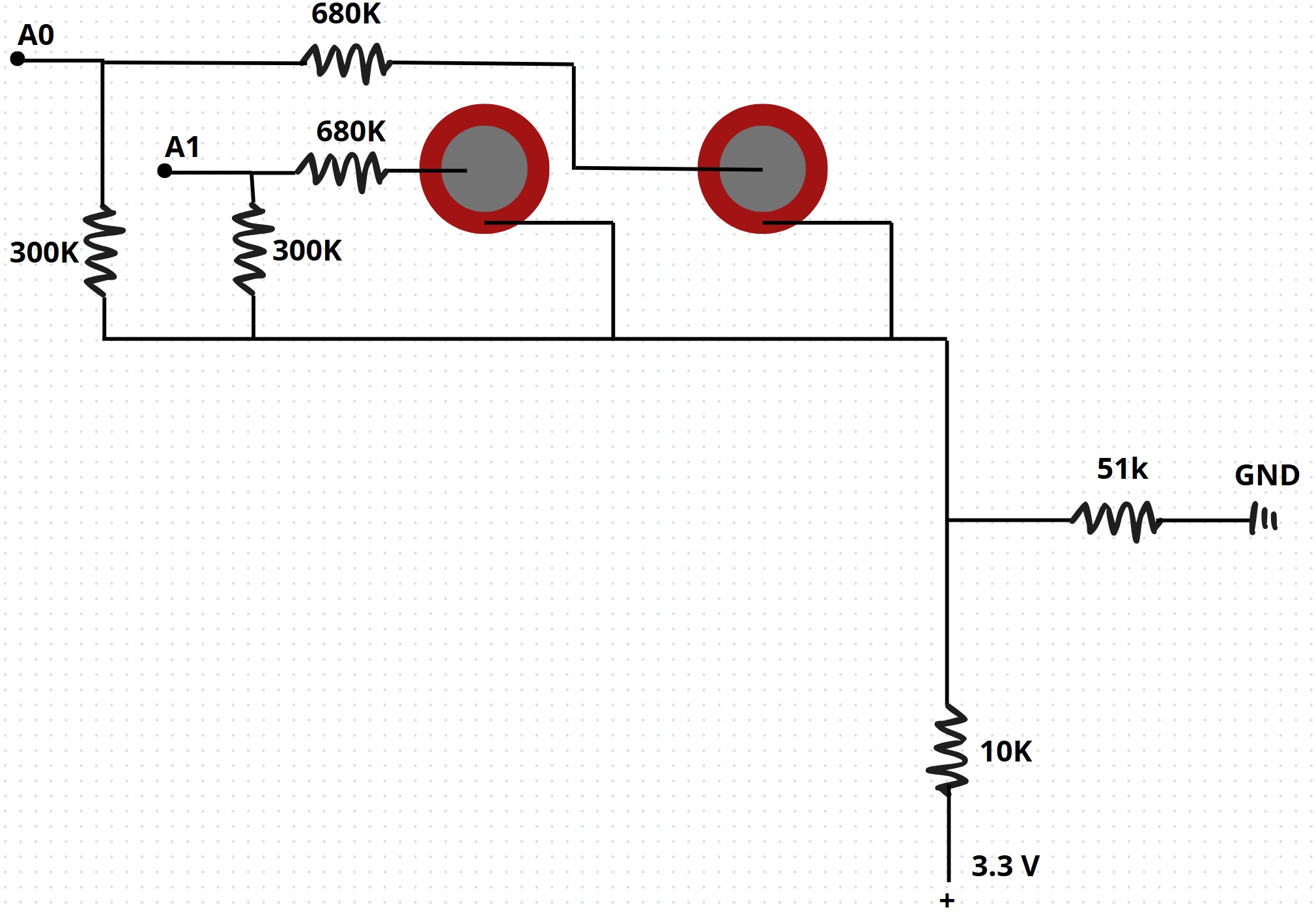
Your divider network is equivalent to 2.76V R 8.4k ; that really should be in the centre of the voltage range for the portenta adc to allow for positive and negative swings - assuming the pressure is not unidrectional.
Sorry, I forgot to use the acronym of PLA (Polylactic Acid). From the resistors point of view I know that they are not perfectly equal but I don't have 820k and 18k (the resistor without value in the paper) in the set of resistors that I have. The closest resistors to 820k are 680k or 1M, and to 18k are 22k or 10k. I thought that small differences were not a very big problem.
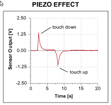
Its a very poorly presented graph, my Uni lecturer would have me drawn over the coals for not providing units for the axes,
However, note the input sample goes below zero, with a piezo element as small as yours, it is possible to produce more than 5V peak to peak output, in fact hundreds of volts if hit hard enough.
You need to provide some diode protection to the Arduino analog inputs even though you have potential divider networks.
Also the cited project uses a Arduino NANO 33 BLE, you are using a Arduino Portenta H7, I'm not familiar with all the newer controllers, but is their performance similar?
Yes in the figure it's 18k but since there were problems I tried more than 22k to check if it could work. I have 300k resistors so I can use the same value for them.