Hello, I'm trying to use the ADC in continous mode. As far as I see it works, except the Vref measured on the external pin starts falling to 2.6V or soo after some ms after the ADC is started.
Being like this the values that I get from the conversion of a constant dc value look like a rising exponential waveform.
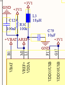
From the schematics of the Portenta I see the Vref is derived from an internal 3.1V with a 100k ohm resistance and a 100nF capacitor. For me it seems the ADC is drawing some current from that and the voltage falls with a time constant defined by the RC.
Any work arround for this? Or is just the ADC functionality is useless with the internal Vref?
If you use more than 8 Bit, the ADC is not really precise.
You can use an external VREF, connected to the AREF header pin, which works great.
The STM chip has internal VREFs too, so you can try these if you want.

You should definitely take a look at this datasheet : https://www.st.com/resource/en/application_note/an5354-getting-started-with-the-stm32h7-series-mcu-16bit-adc-stmicroelectronics.pdf
Link?
page 2...
Since we dont know what is connected INSIDE the chip those connections arent very meaningful
How are you measuring that?
Can you provide your code for the ADC measurement program, and a schematic of eveything you have connected to the Portenta - including how it is powered?
Corrected link from post 2
Right now I´m powering the Portenta with the usb with a 2A charger.
Nothing is connected to it and the measurement of the Vref is made between pin AREF and GND according to the pinout from the arduino documentation.
This is what I get in the oscilloscope:

And the code:
#include "main.h"
#include <WiFi.h>
#include "arduino_secrets.h"

///////please enter your sensitive data in the Secret tab/arduino_secrets.h
char ssid[] = SECRET_SSID;    // your network SSID (name)
char pass[] = SECRET_PASS;    // your network password (use for WPA, or use as key for WEP)
int keyIndex = 0;             // your network key Index number (needed only for WEP)

int status = WL_IDLE_STATUS;

WiFiServer server(80);


ADC_HandleTypeDef hadc1;
TIM_HandleTypeDef htim16;

void SystemClock_Config(void);
static void MX_ADC1_Init(void);
static void MX_TIM16_Init(void);


const int   TxPin        = 0;               // transmitter pin
const int   ledPin       = LED_BUILTIN;     // pin to use for the LED


uint16_t    raw = 0;
const uint32_t    data_len = 5000;
uint16_t    data[data_len];
uint16_t    data_bool[data_len];
uint8_t     adc_delay = 2;

void setup() {
  // put your setup code here, to run once:

// WiFi configuration follows
Serial.begin(9600);
//  while (!Serial) {
//    ; // wait for serial port to connect. Needed for native USB port only
//  }

  Serial.println("Access Point Web Server");

  // by default the local IP address of will be 192.168.3.1
  // you can override it with the following:
  // WiFi.config(IPAddress(10, 0, 0, 1));

  // The AP needs the password be at least 8 characters long
   if(strlen(pass) < 8){
    Serial.println("Creating access point failed");
    Serial.println("The WiFi password must be at least 8 characters long");
    // don't continue
    while(true);
  }

  // print the network name (SSID);
  Serial.print("Creating access point named: ");
  Serial.println(ssid);

  //Create the Access point
  status = WiFi.beginAP(ssid, pass);
  if (status != WL_AP_LISTENING) {
    Serial.println("Creating access point failed");
    // don't continue
    while (true);
  }

  // wait 10 seconds for connection:
  delay(5000);
//
  // start the web server on port 80
  server.begin();

  // you're connected now, so print out the status
//  printWiFiStatus();

// ----------------  end of wifi config


  HAL_Init();
//  SystemClock_Config();
  MX_ADC1_Init();
  MX_TIM16_Init();
  MX_GPIO_Init();


  HAL_TIM_Base_Start(&htim16);

  Serial.println('Setup finished');
}

void loop() {
  // put your main code here, to run repeatedly:

// Communications
// compare the previous status to the current status
  if (status != WiFi.status()) {
    // it has changed update the variable
    status = WiFi.status();

    if (status == WL_AP_CONNECTED) {
      // a device has connected to the AP
      Serial.println("Device connected to AP");
    } else {
      // a device has disconnected from the AP, and we are back in listening mode
      Serial.println("Device disconnected from AP");
    }
  }

  WiFiClient client = server.available();   // listen for incoming clients

  if (client) {                             // if you get a client,
    Serial.println("new client");           // print a message out the serial port
    String currentLine = "";                // make a String to hold incoming data from the client

    while (client.connected()) {            // loop while the client's connected

      if (client.available()) {             // if there's bytes to read from the client,
        char c = client.read();             // read a byte, then
        Serial.write(c);                    // print it out the serial monitor
        if (c == '\n') {                    // if the byte is a newline character

          // if the current line is blank, you got two newline characters in a row.
          // that's the end of the client HTTP request, so send a response:
          if (currentLine.length() == 0) {
            // HTTP headers always start with a response code (e.g. HTTP/1.1 200 OK)
            // and a content-type so the client knows what's coming, then a blank line:
//            client.println("HTTP/1.1 200 OK");
//            client.println("Content-type:text/html");
//            client.println();

            client.println("Begining of data block");
            for(int i = 0;i<data_len;i++){
              client.println(data[i]);
              //delay(1);
            }
            client.println("End of data block");

            // The HTTP response ends with another blank line:
            client.println();
            // break out of the while loop:
            break;
          } else {      // if you got a newline, then clear currentLine:
            currentLine = "";
          }
        } else if (c != '\r') {    // if you got anything else but a carriage return character,
          currentLine += c;      // add it to the end of the currentLine
        }


      }
    }
    // close the connection:
//    client.stop();
//    Serial.println("client disconnected");
  }


// Com end


noInterrupts();                                              // Very important: Stops any interrupts that would cause the program to hang and stay in one state for up to 4us. See: https://forum.arduino.cc/t/fast-gpio-toggle-with-portenta-h7-using-hal/682470

//HAL_GPIO_WritePin(GPIOH,GPIO_PIN_15, GPIO_PIN_SET);    // Set PH15 to HIGH
HAL_ADC_Start(&hadc1);                                // Start ADC conversion
  for(int i=0; i<data_len;i++){

  __HAL_TIM_SET_COUNTER(&htim16, 0);                         // Reset Timer 16 to 0

//      HAL_GPIO_WritePin(GPIOH,GPIO_PIN_15, GPIO_PIN_SET);    // Set PH15 to HIGH


//      HAL_ADC_Start(&hadc1 );                                // Start ADC conversion
      HAL_ADC_PollForConversion(&hadc1, HAL_MAX_DELAY);      // Wait until conversion is finished
      data[i] = HAL_ADC_GetValue(&hadc1);                    // Get ADC value

      while(__HAL_TIM_GET_COUNTER(&htim16)<adc_delay){}      // wait until counter has reached adc_delay counts

//      HAL_GPIO_WritePin(GPIOH,GPIO_PIN_15, GPIO_PIN_RESET);  // Reset PH15 to LOW
 }
//      HAL_GPIO_WritePin(GPIOH,GPIO_PIN_15, GPIO_PIN_RESET);  // Reset PH15 to LOW

 HAL_ADC_Stop(&hadc1);                                // Start ADC conversion
interrupts();                                                // allow interrupts again

//for(int i = 0;i<data_len;i++){
//
//  if(data[i] <= 32768){
//    data_bool[i] = 0;
//    }
//  else{
//      data_bool[i] = 1;
//    }

//    }

delay(1000);


}


// -------------------------------------------------------------------------------
// -------------------------------------------------------------------------------

static void MX_TIM16_Init(void)
{


 // TIM_ClockConfigTypeDef sClockSourceConfig;
 // TIM_MasterConfigTypeDef sMasterConfig;

  __HAL_RCC_TIM16_CLK_ENABLE();                       // f*cking important


  htim16.Instance = TIM16;
  htim16.Init.Prescaler = 200-1;                      // Prescale the system frequency of the processor -> SystemCoreClock is 200 MHz (probably)... at least with 200-1 the timings are correct
  htim16.Init.CounterMode = TIM_COUNTERMODE_UP;
  htim16.Init.Period = 65536-1;                       // count to maximum (16 bit timer)
  htim16.Init.ClockDivision = 0;
 // htim16.Init.ClockDivision = TIM_CLOCKDIVISION_DIV5;
  htim16.Init.RepetitionCounter = 0;
  htim16.Init.AutoReloadPreload = TIM_AUTORELOAD_PRELOAD_ENABLE;


  if (HAL_TIM_Base_Init(&htim16) != HAL_OK)
  {
    Error_Handler();
  }


}
// -------------------------------------------------------------------------------
// -------------------------------------------------------------------------------
static void MX_ADC1_Init(void)
{

  /* USER CODE BEGIN ADC1_Init 0 */

  /* USER CODE END ADC1_Init 0 */

  ADC_MultiModeTypeDef multimode = {0};
  ADC_ChannelConfTypeDef sConfig = {0};

  /* USER CODE BEGIN ADC1_Init 1 */

  /* USER CODE END ADC1_Init 1 */
  /** Common config
  */
  hadc1.Instance = ADC1;
//  hadc1.Init.ClockPrescaler = ADC_CLOCK_ASYNC_DIV1;
  hadc1.Init.ClockPrescaler = ADC_CLOCK_SYNC_PCLK_DIV1;
  hadc1.Init.Resolution = ADC_RESOLUTION_16B;
  hadc1.Init.ScanConvMode = ADC_SCAN_DISABLE;
  hadc1.Init.EOCSelection = ADC_EOC_SINGLE_CONV;
  hadc1.Init.LowPowerAutoWait = DISABLE;
  hadc1.Init.ContinuousConvMode = ENABLE;
  hadc1.Init.NbrOfConversion = 5000;
  hadc1.Init.DiscontinuousConvMode = DISABLE;
  hadc1.Init.ExternalTrigConv = ADC_SOFTWARE_START;
  hadc1.Init.ExternalTrigConvEdge = ADC_EXTERNALTRIGCONVEDGE_NONE;
  hadc1.Init.ConversionDataManagement = ADC_CONVERSIONDATA_DR;
  hadc1.Init.Overrun = ADC_OVR_DATA_OVERWRITTEN;
  hadc1.Init.LeftBitShift = ADC_LEFTBITSHIFT_NONE;
  hadc1.Init.OversamplingMode = DISABLE;
  if (HAL_ADC_Init(&hadc1) != HAL_OK)
  {
    Error_Handler();
  }
  /** Configure the ADC multi-mode
  */
  multimode.Mode = ADC_MODE_INDEPENDENT;
  if (HAL_ADCEx_MultiModeConfigChannel(&hadc1, &multimode) != HAL_OK)
  {
    Error_Handler();
  }
  /** Configure Regular Channel
  */
  sConfig.Channel = ADC_CHANNEL_0;
  sConfig.Rank = ADC_REGULAR_RANK_1;
  sConfig.SamplingTime = ADC_SAMPLETIME_1CYCLE_5;
  sConfig.SingleDiff = ADC_SINGLE_ENDED;
  sConfig.OffsetNumber = ADC_OFFSET_NONE;
  sConfig.Offset = 0;
  sConfig.OffsetSignedSaturation = DISABLE;
  if (HAL_ADC_ConfigChannel(&hadc1, &sConfig) != HAL_OK)
  {
    Error_Handler();
  }
  /* USER CODE BEGIN ADC1_Init 2 */

  /* USER CODE END ADC1_Init 2 */

}
// -------------------------------------------------------------------------------
// -------------------------------------------------------------------------------

void MX_GPIO_Init()
{
  /* GPIO Ports Clock Enable */

 __HAL_RCC_GPIOH_CLK_ENABLE();

 GPIO_InitTypeDef GPIO_InitStruct;

  /*Configure GPIO pin : PH15 */
 GPIO_InitStruct.Pin = GPIO_PIN_15;       // Pin15
 GPIO_InitStruct.Mode = GPIO_MODE_OUTPUT_PP; // digital Output, push-pull configuration
 GPIO_InitStruct.Speed = GPIO_SPEED_FREQ_VERY_HIGH;
 HAL_GPIO_Init(GPIOH, &GPIO_InitStruct);  // GPIO-H
}
// -------------------------------------------------------------------------------
// -------------------------------------------------------------------------------

void Error_Handler(void)
{
  /* USER CODE BEGIN Error_Handler_Debug */
  /* User can add his own implementation to report the HAL error return state */
 // __disable_irq();
  while (1)
  {
    digitalWrite(LEDR, LOW);
    delay(500);
    digitalWrite(LEDR, HIGH);
  }
  /* USER CODE END Error_Handler_Debug */
}

void printWiFiStatus() {
  // print the SSID of the network you're attached to:
  Serial.print("SSID: ");
  Serial.println(WiFi.SSID());

  // print your WiFi shield's IP address:
  IPAddress ip = WiFi.localIP();
  Serial.print("IP Address: ");
  Serial.println(ip);

  // print where to go in a browser:
  Serial.print("To see this page in action, open a browser to http://");
  Serial.println(ip);
}The intention of the code is to send a number of analog measured values to be read in a web browser. Thats why all the code regarding WiFi AP configuration.
That functionality is working, I can connect to the AP and read the measured values.
The problem is the values are wrong... because the Vref is changing.
If you use an external VREF (conntected to the AREF header pin), your results are going to be a lot better!
1 Like
As explained by @timh44 there is a know issue with the Portenta, you must connect an external voltage to have accurate results.
The MachineControl board has a 3.0 V VREF for this purpose.
When I check the schematics: the Vref+ comes via a 100K resistor (R30) from the (external) 3V1 rail.
This rail feeds all the other parts on board. So, it will be pretty noisy.
And: this 3V1 is generated by the PMIC on board (which is a SMPS, switching regulator = very noisy).
You have a dedicated pin for it (JANALOG, pin 1, VREF+).
My question would be: if you feed with (very stable, "noise free") Vref+ - should you de-solder R30 (100K) to avoid the noise still from board via R30 fed in?
I didn't desolder the resistor and my results are pretty good.
Probably you should desolder the resistor.
In my case the VREF = 3V3 and I assume the VCC is 3V1.
Then a current from 2 µA flows to the lower voltage rail.
Doesn't help but works fine for me.
If you want a better accuracy than 8 Bit you need an external VREF.
If I understandt it correctly the external Vref has to be below the 3V1 (or actually about 3.0 as it is my measured value). Am I wrong?
Sorry for not updating; after my initial question I redesigned the application board and included a 3.0V external reference, the Vref pin looks much cleaner now but the ADC result is still noisy, I´m still testing and will try to update.
Thanks for all the hints.
What do you mean by "ADC result is still noisy"?
In which range (how many bits are "of")?
Any ADC has non-linearities and datasheets provide often the inaccuracy, e.g. how many bits are not reliable. It can be up to 2 bits per sample.
A good (external) ADC reference can improve the accuracy, but you cannot overcome the ADC
internal inaccuracy. If chip ADC is specified to be accurate with +/- 2 bits (I do not know real figure here, but possible, it is reasonable to have 2bit error range) - you will get always a "noisy" result.
Analog means often to "round" values, to consider an error margin (+/- tolerance accepted and ignored). It is like floating point: if (float(value) == 0.0) is never TRUE! It can "jitter" around and you have to use a +/-range (error) to say: "OK, this is the value when still inside the range".
Check what the noise level is. Is it changing your result value by 1 LSB (or 2 LSB bits)? This could be still in the valid range for an ADC. Never compare a "bit-exact" value (like a floating point value is never exactly 0.0, never a perfect bit match to get from analog and floating point values).
If your results are still noisy, you can:
- calibrate the ADC with STM calibration routines (offset and linearity)
- use hardware oversampling
- reduce the sampling frequency
I'm having similar issues on a GIGA. ADC readings are inexplicably off by 8% or more. Does anyone know if the STM calibration routines are automatically done by the Arduino (or MBED) analog functions or whether we need to run them ourselves?
I'll also check the Vref ideas mentioned above, hadn't thought of that angle....