Adding LJ8A3-2-Z/BY inductive sensor and counting error

Hi and thank you in advance, nubie here that has so far managed to cobble this together.

I've been whittling away at an agricultural project to count the number of hay bales and flakes per bale going through my small square hay baler, this has been a 3 year on and mainly off project

I have it working, using buttons, to the point where it works with the short leads on the desktop (all but the reset which seems to work in the simulator), but the minute I extend those leads to the 3 meter requirements to reach the baler, it starts playing up and counting itself at times, Iam using shielded (ex cable from a rear view camera) cable, but even if you wave your hands around the Arduino it sometimes adds to the counts.

Q1: would a resistor before the input pin help alleviate these false inputs or is there a way to code it?

end of issue one.

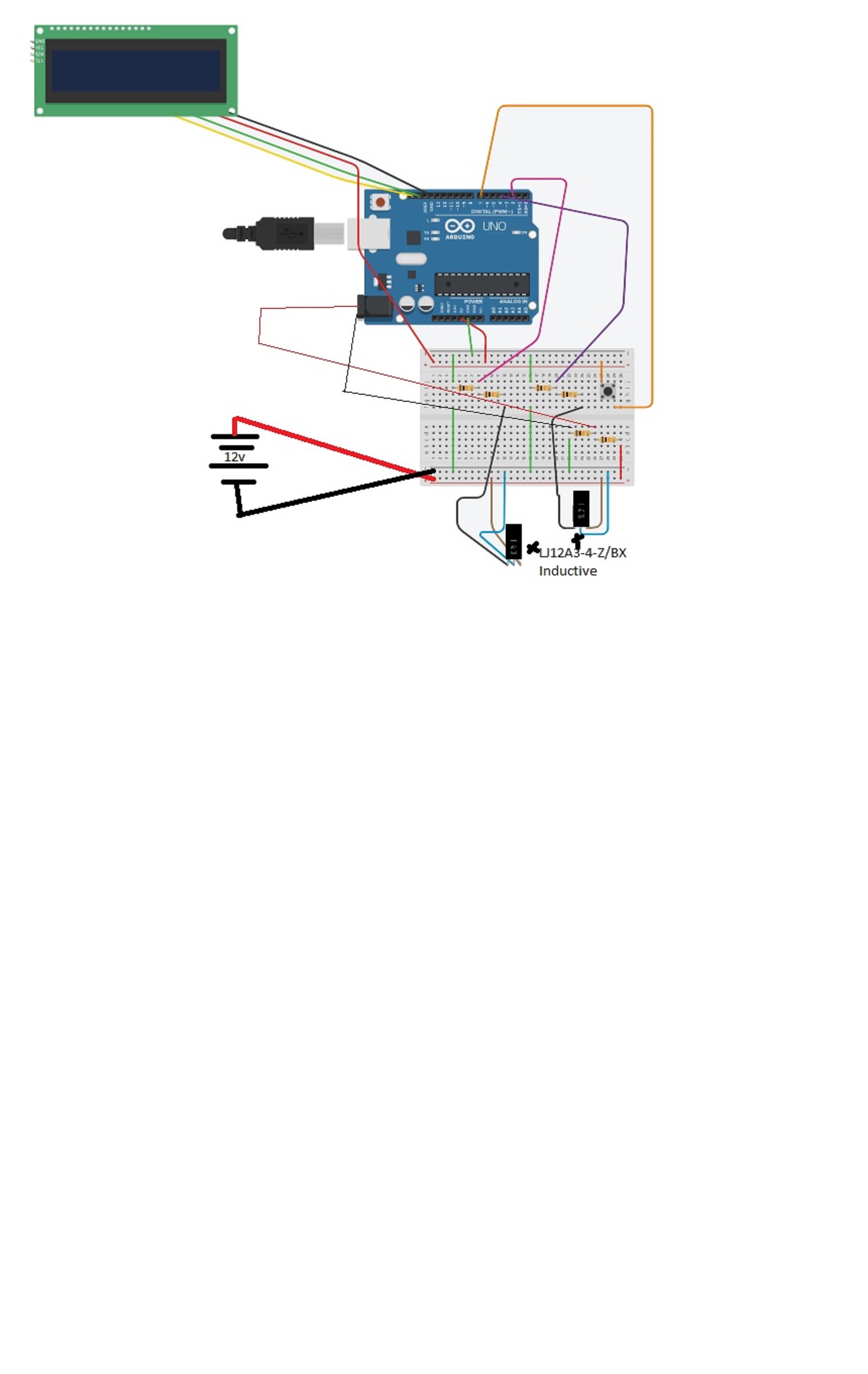
The next progression to move the project off the bench and onto the baler, I wanted to utilize an LJ8A3-2-Z/BY (6-36V) inductive sensor to provide a pulse (on the tinker cad it is replacing the left two buttons) sending a 12v signal back to the control box, which I then have to reduce to the 5v for the pin ins.
I im using an existing bolt on the plunger crank arm to trigger the flake count and the pin that counts the bales mechanically.

on the picture, left button is bale trigger (pink), middle is flake (purple) and right is reset (tan).

Q2: I am basically out of my depth with electronics learning on the fly.
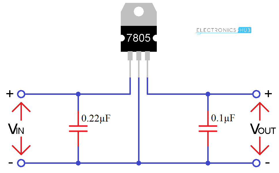
I was thinking of using 12v to the sensor and returning to the enclosure in the cabin, then using the LM7805 regulator to bring it back to 5v for the input pin. see attached, but will the 5v out create a readable pulse without a -ve back into that circuit.


// C++ code
//
#include <Adafruit_LiquidCrystal.h>

int seconds = 0;

Adafruit_LiquidCrystal lcd_1(0);


//copy from here
int BaleCount= 0;
int PrevFlakeCount= 0;
int FlakeCount= 0;
int LastFlakeCount= 0;
int Bale_Pin= 2;
int Flake_Pin= 4;
int Reset_Pin= 7;
int Light_Pin= 6;


void setup()
{
  lcd_1.begin(16, 2);

  lcd_1.setBacklight(1);
  lcd_1.setCursor(0, 0);
  lcd_1.print("Bales :");
  lcd_1.setCursor(10, 0);
  lcd_1.print(BaleCount);  
  lcd_1.setCursor(0, 1);
  lcd_1.print("Fl:");
  lcd_1.setCursor(5, 1);
  lcd_1.print(FlakeCount);
  lcd_1.setCursor(10, 1);
  lcd_1.print("La:");
  lcd_1.setCursor(14 , 1);
  lcd_1.print(LastFlakeCount);
  
  pinMode(Bale_Pin, INPUT);
  pinMode(Flake_Pin, INPUT);
  pinMode(Reset_Pin, INPUT);
  pinMode(Light_Pin, OUTPUT);
}

void loop()

{
  //Print onto LCD

  { 
    lcd_1.setCursor(10, 0);
    lcd_1.print(BaleCount);
    lcd_1.setCursor(5, 1);
    lcd_1.print(FlakeCount);
    
  }
    
  
 //Reset Bales
  if (digitalRead(Reset_Pin) ==HIGH)
  {
   BaleCount=0;
   FlakeCount=0;
   PrevFlakeCount=0;
  }
 
  //bale count
  else if (digitalRead(Bale_Pin) == HIGH)
  { 
    BaleCount++;
    FlakeCount=0;
    lcd_1.setCursor(5, 1);
    lcd_1.print("    ");
    lcd_1.setCursor(14 , 1);
    lcd_1.print("    ");
    lcd_1.setCursor(14 , 1);
    lcd_1.print(PrevFlakeCount);
    PrevFlakeCount=0;
  }
   

  //Flake count
   else if (digitalRead(Flake_Pin)== HIGH)
  {
      FlakeCount++;
      PrevFlakeCount++;
  }
  
  
}
  

Personally i would add some bulk electrolytic caps to the 7805. Say some 4.7 to 10 uf on input and 47 uf to the output. Your caps filter out high frequency noise and that's good.
Please post a schematic showing the troubeling setup, and a datasheet link to that sensor.
I see no sensor connected.
Please drop those Fritzing toys. No helper likes them.

I think i understand what you are saying with the caps, I will work out how to put that into the design.
The part with the 12v inductive sensors is still in my head, I know what I need, just trying to learn how to achieve it.
Basically the S2 and S1 are what iam using as triggers in testing but moving forward they have to be replaced by inductive sensors, I know i have to use the regulators as per the other diagram, but obviously the 5v out will not have a -ve unless i some how patch the arduino ground to that ( and dont know if that will blow it up)

like I said, this is a learn on the job because I have been bouncing this "make my life better" idea around my head for years, its my first project that is not the basic cut and paste basic learning type, I know i have chewed of a big bite first time out as I have no back ground in electronics but trying to learn.

What do you mean by fritzing toy (i know fritzing is a PCB design program)

Inductive Proximity Sensor LJ8A3_Inductive Proximity Sensor_Photoelectric Sensor_Capacity Sensor_Solid State Relay_PCB Relay_Timer Relay (control-electrical.com)

Bale Counter (1).pdf (6.3 KB)

Please post schematics showing what You're heading for. Triggers here and other stuff there.... Words is not the way to describe the project. They give no over all picture.

I think i have solved it partially with resistors rather than regulators, it seems to work on the bench no drama atm including using LJ12A3-4-Z/BX Inductive Proximity sensors ( i know i used IR sensors in the schematics, but that was the only 3 prong sensor tinker cad had)
if I put a capacitor between the input of pin 2 & 4 and ground, will that solve my interference issue.

Here are the current schematics that seem to work:
Copy of Bale Counter.pdf (5.8 KB)

The button connections on your first picture won't work correctly, you need a 10k pulldown resistor from input pin to GND.
If you are using 12V for the prox switches (PNP open collector), then a 10k / 10k divider will put 6V on the input pins causing the protection diodes to conduct a few microAmps. I would use R1 = 9.1k and R2 = 5.6k dropping 12V to 4.6V.

RIght, i know max voltage on the pins is 5.5v, but must be 3 volts to register, when I bench tested it with a 9v battery, the ouput on the pin was 2.9V, so I was woried about the extra battery power once I put it in the tractor, if you look at the current revision of the same picture, you can see I've put in the sensors ( which seem to work fine on the bench) and added the 12v system, which gets pulled down to supply the arduino ( i figured it will handle the 12v, but the voltage would be more stable if I did this).

As I have said before, my electronic knowledge is still super basic, it only goes as far as knowing what I want and part names, I have been using google, my long lost programming logic learned on an apple IIe in high school and some lateral thinking to get to this point, so I really appreciate your input.

So if I change those resistors from 10k to the 9.1k and 5.6k, it will drop voltage going to the pin, not increase it.

I know its not a proper schematics, but not sure how to add the 12v and proper sensors in tinker cad.

Well, that throws a clinker into the works! You realize that the voltage from a 12V battery being charge by an alternator could exceed 14V + all the noise from ignition and fuel injector pulsing?
Methinks you should use optocouplers to isolate the prox sensor signals to the Arduino.

Yeah, I was a mechanic many moons ago, so I do know about the voltage fluxuating from the alternator and interference from other systems , that’s why I wanted to regulate the voltage to around 9v with r6&7 ( i think those are the one to do that) hoping it would smooth out the signal, the other option was to rat a cigarette lighter charger 12v>9v and use that to power the whole thing and smooth out the signal.
Lucky it’s a diesel and the injectors etc are all mechanical so shouldn’t interfere, the light bar may however be an issue as it interferes with the radio.
The only drama I have had and is next on the progress list, any interference coming back to the digital in pins, as soon as I put leads long enough to reach the baler I get random ^ in counts, mind you this is before I installed the resistance.

This topic was automatically closed 180 days after the last reply. New replies are no longer allowed.