I brought LJ18A3-8-Z/BY Inductive sensor for a metal detecting robot. connections are:
black- digital input 7
brown- 9V
blue- gnd
when the sensor is brought close to a metal the led on the sensor lights up which indicates that the sensor is working but the signal sent to arduino is not correct.
I get a floating output of zeros and ones in arduino serial monitor.
the code i m using is
int val;
void setup()
{

Serial.begin(9600);
pinMode(7, INPUT);
pinMode(13, OUTPUT);
}

void loop()
{
delay(100);
val=digitalRead(7);
Serial.println(val);
if(val == HIGH)
{
  digitalWrite(13,HIGH);

}
else
{
    digitalWrite(13,LOW);

}
}
i have also checked the sensor output using a multimeter which shows:
8V when not metal is present and
0V when metal is present.
i have converted the 8v to 4v for input to the digital pin for safety of arduino. Still not working. please help ASAP.
i have converted the 8v to 4v for input to the digital pin for safety of arduino.
How? Post a wiring diagram (hand drawn, not a Fritzing mess).
thanks a lot for replying.
i have attached the diagram.
[update] i also tried to run the ReadAnalogVoltage example by connecting to sesnor's output to A0 pin. doing this also showed bad values....not the one i m getting on multimeter.
i m not able to get the problem.
As you have discovered, that circuit won't work.
The sensor you have, according to this seller, has a PNP output, which must be connected to ground with a resistor.
To lower the output voltage to 0 to 5V for the Arduino, use a voltage divider as shown below.
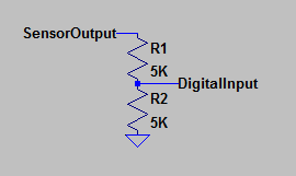
The sensor is intended to run on 10V, minimum.
Still the same output.
the sensor i received is a PNP NC because when no metal is detected the output is 12V when i gave it 12V supply.
when metal is present the output is 0V.
Sorry for the wrong information, i checked that on the sensor itself is LJ18A3-8-Z/BX.
please give a circuit for this sensor. thanks for replying.
the sensor i received is a PNP NC because when no metal is detected the output is 12V when i gave it 12V supply.
when metal is present the output is 0V.
In that case, the circuit I posted will work fine, except change the voltage divider to R1= 6.8K, R2= 4.7K to avoid >5V on the input pin.
The following statement contradicts the one above. But the above circuit will work in either case.
Sorry for the wrong information, i checked that on the sensor itself is LJ18A3-8-Z/BX.
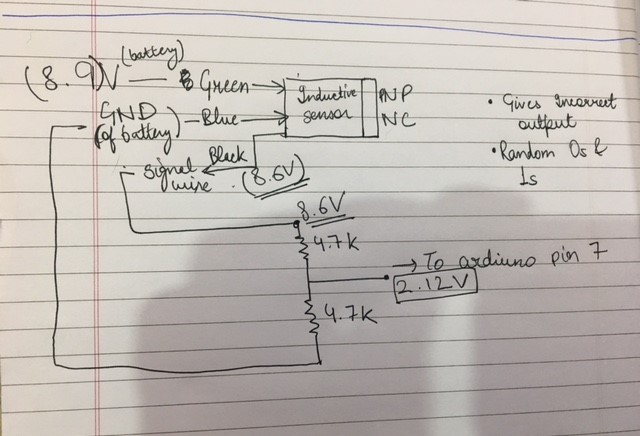
I kind of found the problem. the problem is of ground. i have attached two images to show this.
All the voltage values are obtained from Multimeter.
First image is drawn with black ink(INCORRECT_CONNECTION_BLACK) which shows that:
the sensor output is not equal to sensor input i.e 8.9V.
the voltage divider should give output (8.9*0.5= 4.45) as R1=4.7k and R2=4.7k but shows output 2.12V
please help me solve this issue.
this connection gives bad output.
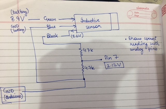
Second image is drawn with blue ink(CORRECT_BLUE):
When i connect GND of arduino to the GND of voltage divider the ReadAnalogVolage code it shows correct output i.e 2.12(but i want 4.5V o/p so it is read by digital pin).
Since i m unable to get correct output voltage from voltage divider i changed my code to
reading = analogRead(A4);
Serial.print(reading);
Serial.print("\n");
metal = (float)reading*100/1024.0;
Serial.print("Metal in Proximity = ");
Serial.print(metal);
Serial.println(" %");
if(reading<300)
Serial.println("Metal Detected");
delay(100);
this does the magic but i want the signal to be read on a digital pin.
i also directly connected the sensor output to pin 7 and is works there too for this code
the code i m using is
but for the safety of my arduino please help me to rectify my voltage divider output and it would be great if u could explain me why the arduino GND helped.
Forgive me if the images are shabby i m new to the forums.
thanks again for replying jremington
You must ALWAYS connect the grounds, as it establishes the zero voltage reference.
If the voltage divider output measures 2.12 V with respect to battery negative (ground), then you either have wiring error or a component error.
Double check the resistor values. If they are equal, the voltage at the divider will be 1/2 of the input voltage.
