I was going to include a couple of voltage regulators to separate the processor from the motors and include 5 or 6 male pin "slots" for hobby servos with separate power and signal from the processor. Plus maybe some leds to indicate servo function. For power to the board I was going to use some little screw lugs so it will be easy to switch from different battery packs to bench power etc.
I was also going to include a couple of 2X3 plugs for plugging other stuff into the board in the future. Maybe have them break out 5V and GND along with some pins.
Any advise/ideas would be great! Especially on laying out components on the prtoboard. I'm going to start with paper instead of the soldering iron this time
I was also wondering about what pinout I should use for this cable:
I've been programming my other little board with individual jumpers but I decided to make a cable so I wouldn't have to fiddle with wires so much. I'm only using RX, TX, reset, 5V, and GND and the 6th wire will be unused. Any advise on how to wire the pins to the cable or just go with what feels good?
Connect 6th wire to Gnd. Then when you use and FTDI Basic to program with, the 6th wire will go to CTS pin on the FTDI Basic.
Wire the header so the FTDI Basic can plug into the end directly.
CrossRoads:
Connect 6th wire to Gnd. Then when you use and FTDI Basic to program with, the 6th wire will go to CTS pin on the FTDI Basic.
Wire the header so the FTDI Basic can plug into the end directly.
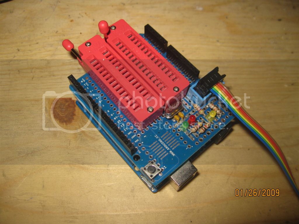
Thanks! Using this board as a reference:
Which pinout would be the best route. the "basic" side? If/when I get an FTDI cable/board it would be nice to keep the ribbon cable flat instead of having wires crossed over!
I really appreciate the advise. I have very little hindsight to help me with these things!
Now I have to use 5 jumpers from the UNO to program my standalone project and it's a little cumbersome plugging/unplugging them when testing sketches. My idea was to put a 2X3 on my UNO and another on my project(s) and use the ribbon cable for programming.
I would like to do the pinout in a logical manner so if I get a proper FTDI device in the future I can make a cable that will go from the 2X3 plug (On my projects) to the straight header deal that most FTDI devices use.
I'm laying out the components on my protoboard now. Any advise on how this stuff is normally done? I'm just placing stuff on there and playing it by ear.
Well, you could put 2 headers on your board - an ICSP 2x3 header with 6 pins for bootloading: D11-D12-D13, +5, Gnd, Reset.
and a 1x6 header for FTDI: Rx, Tx, +5, Gnd, Reset, 2nd Gnd.
You can see how I did that on a board here http://arduino.cc/forum/index.php/topic,112020.45.html see reply #52.
As far as parts placement, every thing connects to the uC in general, yes? So make that central and try to keep traces short with as few crossing sginals as possible to minimize vias.
I'm using the shield with the ZIF sockets to bootload the chip. I didn't think I would have to deal with that anymore once it was done so I was only concerned with programming once it was put together. Should this be a problem?
I also figured I could make an adapter cable in the future if I went with an FTDI programmer. A little cable with a straight header on one end and a 2X3 (Or is it 3X2?) plug on the other.
The power input is on the left with a 7805 for the uC and the one with the heat sink for the servo motors. The male pins on the right will be for the servos to plug into with power coming straight from the VR and the 3rd pins going to the uC. I'm going to place a female header across the top and perhaps some leds.
The crystal and caps are hidden by the heat sink.
I have a 1000 uf cap where power enters and I'm going to put 0.1 uf caps across the VRs, a 100 uf cap before the uC as well as 2 more 0.1 uf caps near the VCC of the uC. I also have a 10 uf cap near the uC.
On earlier experiments I just had the Aref pin floating (Which worked fine) so any input on properly dealing with it would be most welcome!
I should have used a socket but this chip has a wonky leg plus I don't want to trek to RS today
Thank's a million for the help!
The next thing I want to get into is switching regulators...
For information on moving an Arduino project to dedicated hardware and how to make up a cable to use an Arduino as ISP, see Prototyping small embedded projects with Arduino | David Crocker's Solutions blog. Unless your project needs to talk to a PC, you don't need to bother with the FTDI (serial-to-USB) converter or a bootloader, you can program your sketch directly into the target mcu, as long as you include an ICSP header in the design.
Use a piece of tape on the component side. Make sure things are lined up square. Solder an end pin, check the fit solder the other end or adjust as needed.
Instead of running wires everywhere like the last project I just connected the dots. I hope it doesn't cause any problems.
I ran 2 power rails down the center of the chip and put 10 uf and 0.1 uf caps on either end plus a 220 uf cap across the lines further "upstream". There is also a 1000 uf cap before the regulators. The other version worked fine with only the 10 uf cap but I wanted this one to be a little better. I also made sure that all the wiring so far stayed away from the pins that I need to break out. I had a lot of stuff in the way with the other version.
I guess since all the life support is in place for the uC I need to wire up the programming stuff and see if everything is OK.
Does anyone see any obvious problems?
I thought I fixed the date on my camera... Oh well, it didn't stick.
From the photos it appears to me that you have two TO220 devices bolted using a single bolt to one heatsink. I guess one is the power regulator, but what is the other one? The tab of a TO220 device is normally connected to one of the pins, so the bolt may be making an unintended connection between the two devices.
dc42:
From the photos it appears to me that you have two TO220 devices bolted using a single bolt to one heatsink. I guess one is the power regulator, but what is the other one? The tab of a TO220 device is normally connected to one of the pins, so the bolt may be making an unintended connection between the two devices.
Those are 2 7805's. I checked the pin out and the lug is connected to ground. I did have an issue with the last board I put together this way though. The VR's were wired in parallel (Input voltage only) with the output from one VR going to the uC and the output from the other going to the motors. One put out a solid 5V and the other one waffled around 3V. I'm not sure what was going on but if this one does the same thing I guess I'll have to re-think running 2 VR's this way.
At least I can upload sketches and blink led's. I'm hoping the motor driving part of it works OK.
I was thinking about putting an LM 298 and some lugs on the blank side of the board so it could drive regular DC motors (Maybe a Tamiya gear motor setup) as well as the servos. I haven't fooled with 298's yet but driving regular motors sounds cool.