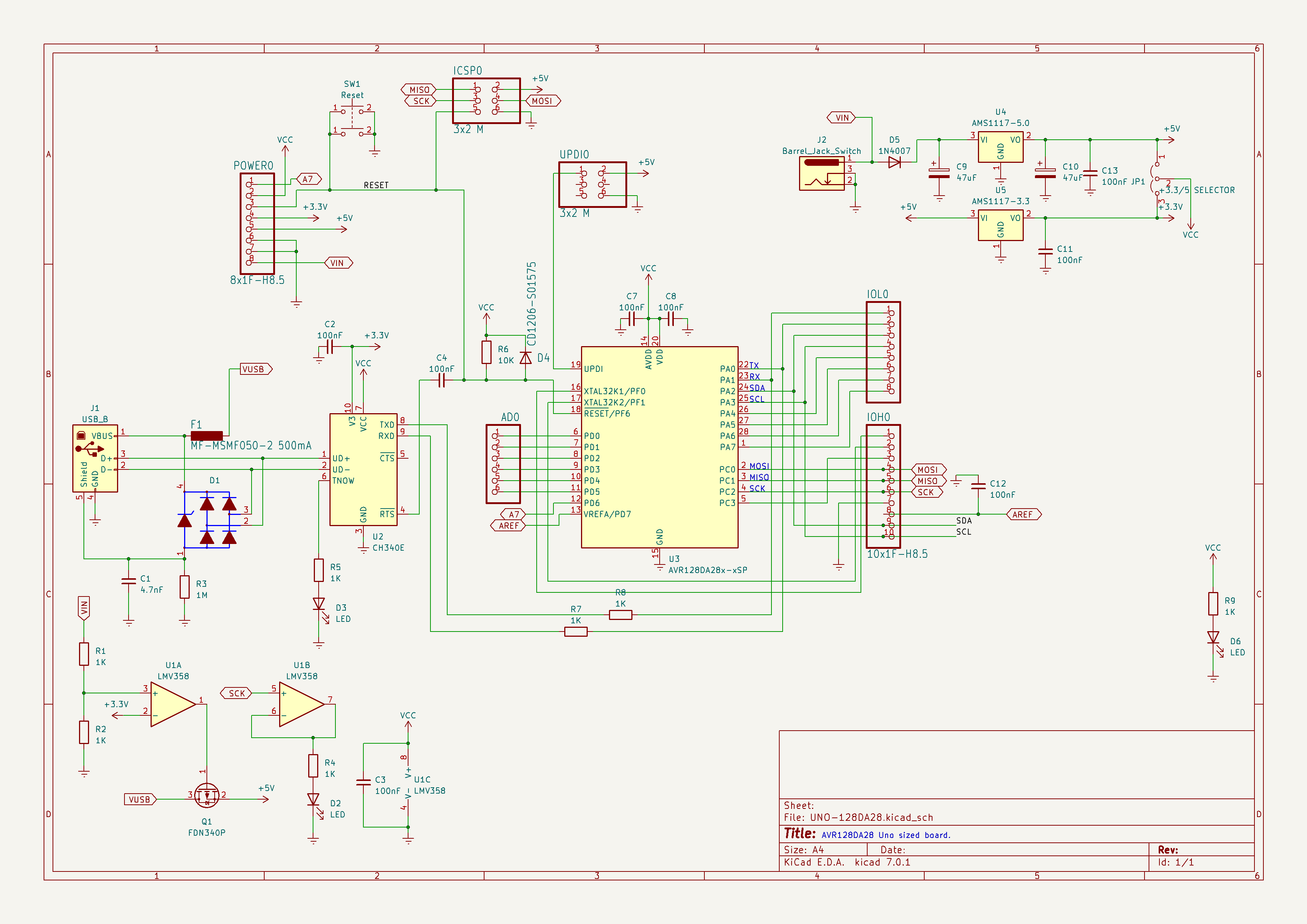
I have been developing a AVR128DA28 based board,
Trying to keep the pin layout the same as a normal Uno R3.
I will probably use @DrAzzy core for the board and adapt it to suit.
End goal will to have a "more" compatible Uno R4(being an AVR) option.
What is everyone's thoughts/suggestions for the project.
Looks pretty good to me.
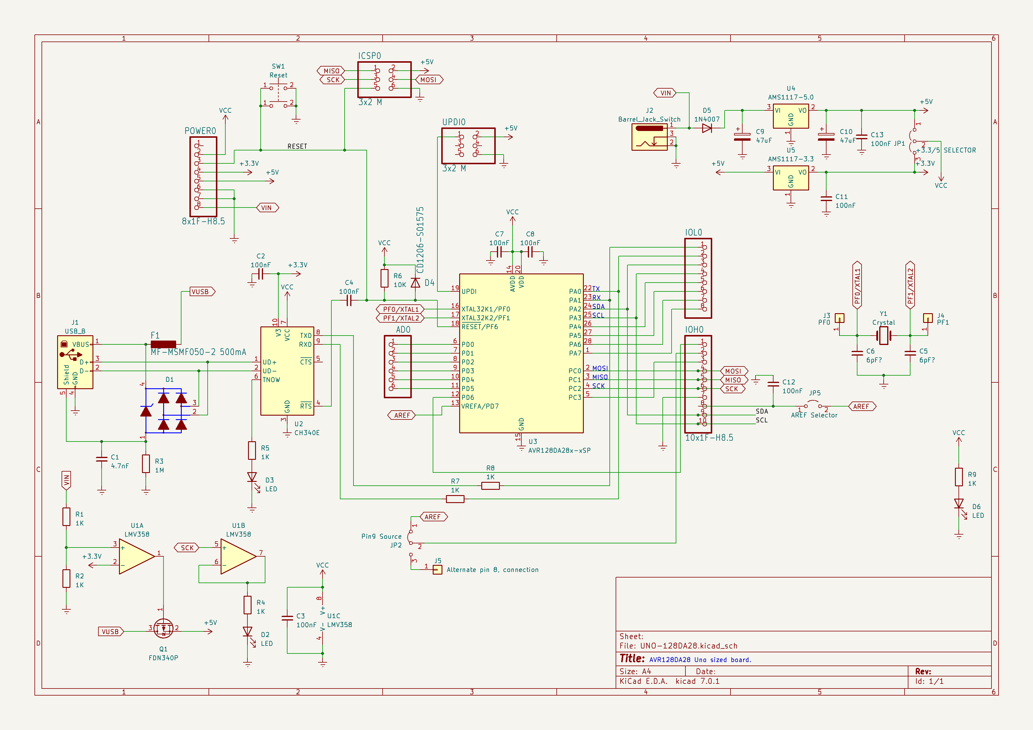
I've worked on similar and had "issues" deciding whether I would rather have a crystal, or lose a digital pin.
I'm not sure I'd dedicate a whole 6pin connector to UPDI. "Many" of the UPDI programmers (homemade, PicKit4/5, SNAP) don't come with a 6pin programming cable by default, anyway.
What would you recommend, a 3pin connector or add RX/TX to the header?
I use this pinout when I design boards, but I happen to sell programmers at Tindie that are compatible with this pinout (MicroUPDI and SerialUPDI).
However, with this pinout, you can still use the Atmel ICE, JTAGICE3, and the Power Debugger without any modifications or adapters.
The PICkit4 or MPLAB SNAP uses a 1x8 header instead of the typical 2x3 header. However, they can also be used as USB to serial adapters while still being UPDI programmers. So with a simple adapter board, you can use the PICkit4/SNAP with this 2x3 pin UPDI pinout, where you can program and debug using the UPDI pin, and send data back and forth using UART.
On my DA-based board (which has not been fabbed or tested), I added a UPDI pin just below the SPI connector.
That way it only adds one new pin to the board, and there is still access to VCC and GND.
(Oh, and I got rid of AREF. It's seldom used, awkwardly placed, and rather obsolete given the greater set of internal references on a AVR-DA.)
The reason I never use Uno-shaped boards is that, in order to maintain compatibility with shields and code written for them, they have to assign pin numbers in ways that made sense on a 328p but make very little sense on a AVR Dx or later. The pins are always scrambled up as they have to be to work with the shields. And shields are expensive as hell and I can't afford that kinda thing. (How do you calculate the price of a shield? Find simple breakout module that does the same thing, and note the price it's selling for. Move the decimal one place to the right, and that's the price for the shield eyeroll)
This wasn't entirely constructive, but I do think it underscores the fact there may be less overlap between people who want uno-shaped things and people who want DA's. I don't know. My disdain for shields may be another way in which I'm a whackjob.
Nice board, I see you have the external crystal.
I may just follow your board layout for pins 8 & 9(chip pins 12&13), and provide the space and hardware for the crystal plus to solderable pads.
I was thinking of having the UPDI pin like you have demonstrated, but ended up buying the 50-mil header .
If you power the CH340N chip from your target voltage select switch you can get it to output 3.3V level signals if you flip. I did this with the SerialUPDI programmer. The V3 pin is the output of the CH340N's internal 3.3V regulator and doesn't need to be connected to anything other than a capacitor
I think the CH340E and CH340N are equal in functionality, so I don't think it's necessary to switch to the CH340E unless you favor its SOIC-8 package.
If you add the analog switch as well (you can use 74lvc1g3157 chips instead if you need something smaller) you can use the CH340N chip as a SerialUPDI programmer that can automatically switch between UPDI and UART mode. I also added a switch (SW3) to override this behavior. The latest version of Avrdude lets you force the state of the DTR/RTS pin, which again controls the UART/UPDI mode switch.
You probably don't need the 74lvc1g125 buffer but I added it to provide a high-impedance RX input and a low-impedance driver for the RX LED.
DxCore is still using Avrdude 6.3, which doesn't even support SerialUPDI programmers. However, Spence himself has said that he will update to the latest version of Avrdude soon.
I'd argue that having a combined UART/UPDI adapter is brilliant when very little extra hardware is required. And as long as the user can override the setting, there are only benefits IMO.
As for the ESD protection, the CH340N datasheet doesn't mention external ESD protection, so I'll assume that the D+ and D- pins have built-in protection. I have yet to see one fail. However, I'd have to make the SerialUPDI PCB larger in order to fit a double ESD diode.