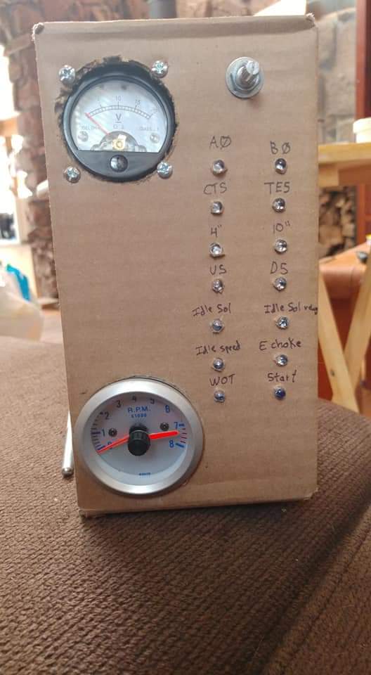
Hello everyone, I have been working on this for the past few weeks, I am essentially building a Bluetooth OBD2 sensor for my vehicle that was made in 1984 (pre-obd anything). The vehicle has diagnostic ports which amount to little more than 0-12v on-off switches in most cases.
I would like to build an Arduino Shield that will interface with an Arduino nano and the vehicle ports. This is my first major project with Arduino, and my first ever electrical schematic so I expect I made a lot of mistakes, but i'm trying right?
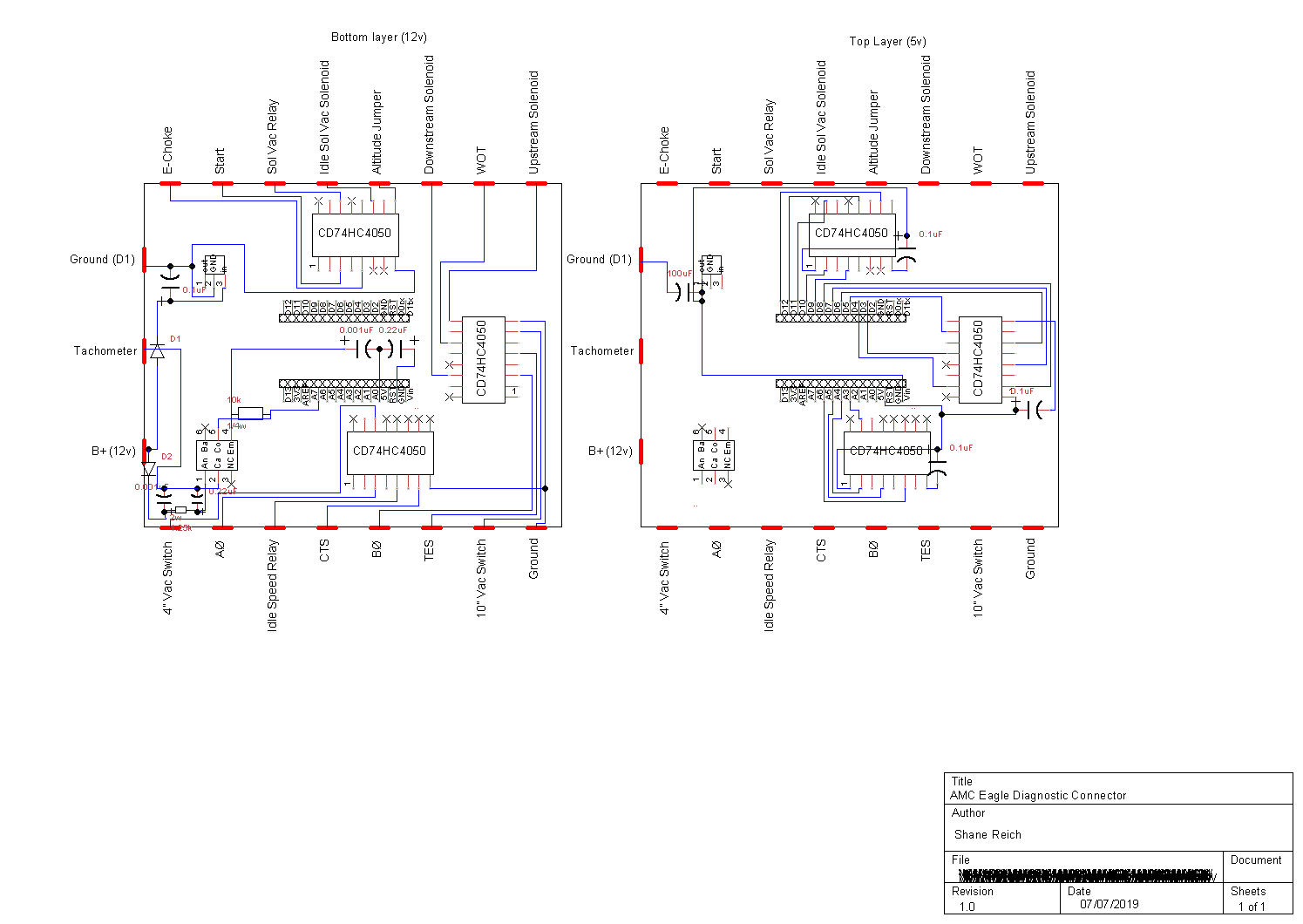
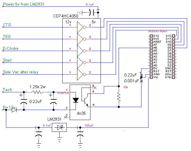
Here is the Schematic as I have made it so far. It was made with TinyCad and I had to custom make the chips because I couldn't locate them. the chips used are LM2931-n for power handling, 4n35 for the Tachometer signal, and CD74HC4050's for the 12v - 5v switch handling. most of these circuits are cobbled together from other circuits so I am not 100% sure if I did them correctly. the red dashes along the outside are where I would solder wires for the vehicles connectors. It is a 2 layer board with most of the 12v side on one side and the 5v on the other for separation and ease of routing. all components will be thru-hole to make it easier to solder and I don't have too much of a size constraint
my main questions are: does this layout look logical, is there a better way to do this? did I make any mistakes that you can see, would I be able to get an accurate battery voltage reading, because that would be a good thing to have, I just don't know how I would drop the voltage down to Arduino levels but still maintain an accurate reading. I of course plan to breadboard all of this before I get the board built.
any ideas, designs, foresight, hindsight, component changes, give up now it wont work's you have are welcome.
If you would like the tinycad files to take a closer look just let me know.
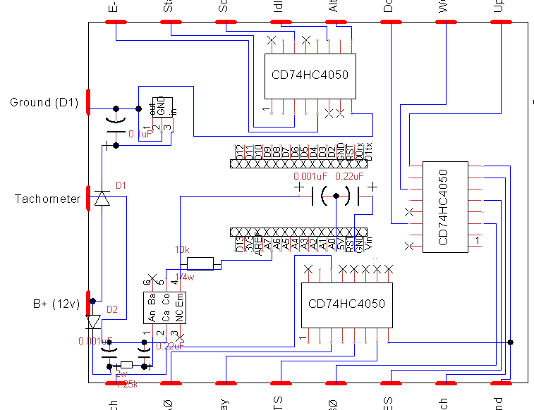
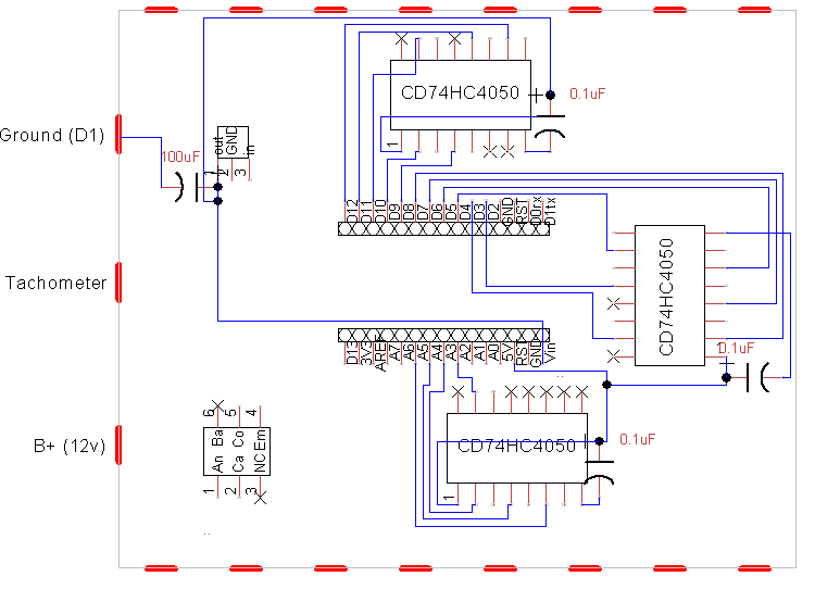
thank you, that was the first thread I read actually. I posted an image, a link to the direct image as well as attached that image to the thread. I would have provided the cad file but I was unable to upload it here. here are attached closer up image of each side of the board. I have not started board layout yet as I am not even 100% sure that I have all the components I need and don't want to have to re-design the whole board each time I have to add or change components.
Vehicle diagnostic signals (12v on off switches) get fed into one of 3 CD74HC4050's that drop voltage down to 5v and send signals to Digital GPIO pins.
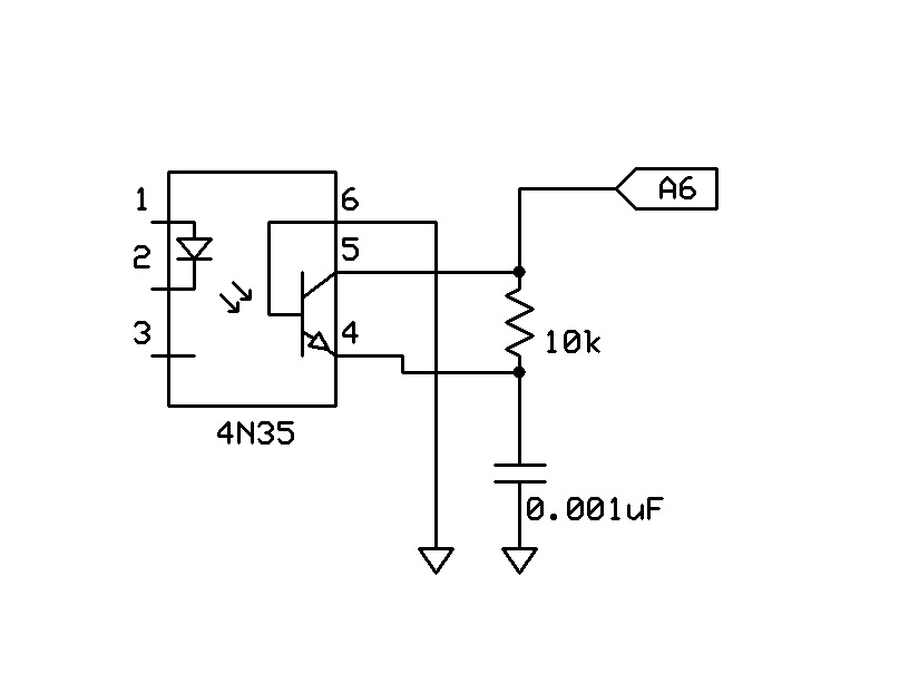
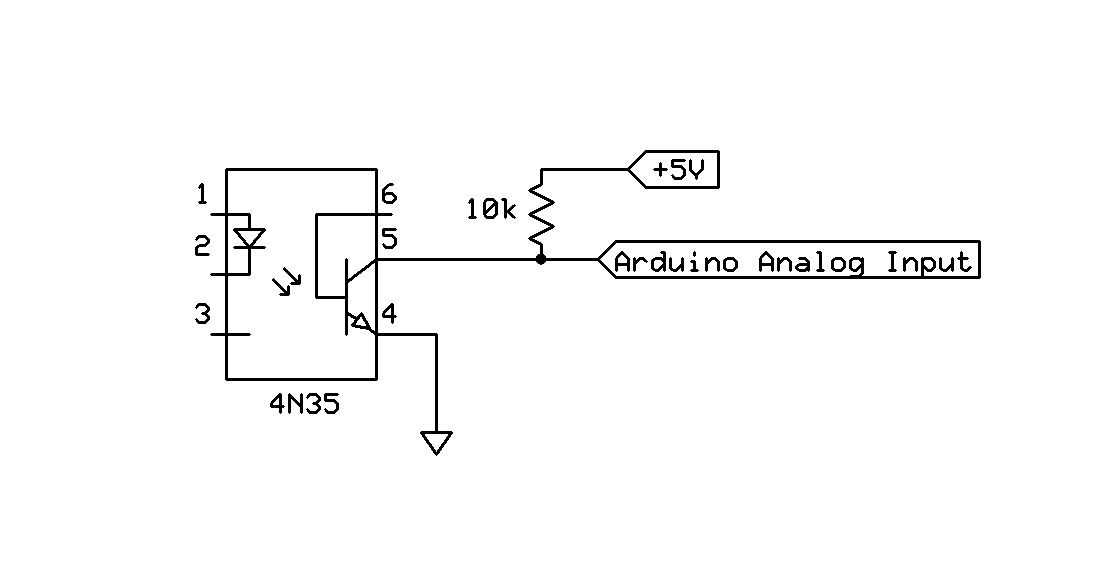
Vehicle Tachometer signal (12v) gets routed thru 4n35 optocoupler using This circuit to make the signal safe for Arduino and plugs into the Analog input.
all of this is powered by the 12v battery in the vehicle that is run thru an LM2931-n regulator.
TomGeorge:
Hi,
Are you going to make a PCB and then test it?
I would be laying everything out with protoboard to get it working, then make a PCB.
Can you tell us your electronics, programming, arduino, hardware experience?
Tom...
I will be breadboarding the circuit first to make sure I have things correct yes, I have all components ordered and on their way now. I have very little arduino experience, worked a tiny bit with raspberry pi, have done other minor code projects for other things, no hardware experience what so ever as far as design goes. I know enough about electronics to get in trouble lol. I've fixed things before, but usually have to Google things to help. I have created a purely analog diagnostic tool for this connector before but the long wires and large box was annoying so I decided I wanted to try to make a wireless one.
here's the code I made so far, I hope it makes sense. essentially I have 2 functions running in loop, one for tach signal, and one to collect and build a small data packet to send over Bluetooth transmission. the serialLoop function is connected to the serialBuild function and checks to see if any information from the inputs have changed, if it has it updates and sends the info packet BTM[] which should be an array of binary that is then sent thru Bluetooth LBT[] array is used to see if individual inputs have changed since last update, and BTO[] is used to see if the whole array has changed since update. the second function is the Tachometer reading which I think will work. it takes pulse inputs from pin 2, does math, then spits out the RPM to serial. it was copied and modified from existing code. this isn't the full code yet, more just to see if im on the right track or way out in left field.
const int tach = 2;
const int cts = 3;
const int tes = 4;
const int start = 5;
const int updateInterval = 200;
unsigned long lastUpdateTime = 0;
volatile int sparkFireCount = 0;
int lastRpmValue = 0;


void serialLoop() {
    BTM[] = BTO[];
    serialBuild(cts, 3);
    serialBuild(tes, 4);
    serialBuild(start, 5);

   if (BTM != BTO){
    Serial.println(BTM[]);
   } else {

}

void serialBuild(pin, i) {

 int val = digitalRead(pin);

  if (val != LBT[i]) {
BTM[i] = val;

  } else {

  }

  BTM[i] = LBT[i];
  }

  void incrementRpmCount () {
  sparkFireCount++;
}


void setup() {
  // put your setup code here, to run once:
int val = 0;
int pin = 0;
int i = 0;

int BTM[] = {};
int LBT[] = {};
int BTO[] = {};
int inMin = 2; // Lowest input pin
int inMax = 12; // Highest input pin
for(int i=inMin; i<=inMax; i++)
{
  pinMode(i, INPUT_PULLUP);
}
pinMode(tach, INPUT_PULLUP);
attachInterrupt(2, incrementRpmCount, FALLING);
  Serial.begin(9600);
}

void loop() {

} if ((millis() - lastUpdateTime) > updateInterval) {

   int currentRpm = (sparkFireCount * (1000 / updateInterval) * 60) / 0.333333333;

   int averagedRpm = (currentRpm + lastRpmValue) / 2;

       Serial.println(averagedRpm);

    sparkFireCount = 0;
    lastUpdateTime = millis();
    lastRpmValue = currentRpm;


  }
   serialLoop()
}
simplified and more functional. made a lot of mistakes previously.
int tach = digitalRead(2);
int cts = digitalRead(3);
int tes = digitalRead(4);
int start = digitalRead(5);
int echoke = digitalRead(6);
int solevacr = digitalRead(7);
int idlesole = digitalRead(8);
int altjum = digitalRead(9);
int dssole = digitalRead(10);
int wot = digitalRead(11);
int ussole = digitalRead(12);
int teninvs = digitalRead(A0);
int b0 = digitalRead(A1);
int a0 = digitalRead(A2);
int idlespeed = digitalRead(A3);
int fourinvs = digitalRead(A4);

const int updateInterval = 200;
unsigned long lastUpdateTime = 0;
volatile int sparkFireCount = 0;
int lastRpmValue = 0;

 void incrementRpmCount() {
  sparkFireCount++;
}

void setup() {
  // put your setup code here, to run once:
  Serial.begin(9600);
int i = 0;
int inMin = 2; // Lowest input pin
int inMax = 12; // Highest input pin
for(int i=inMin; i<=inMax; i++)


{
  pinMode(i, INPUT_PULLUP);
}

attachInterrupt(2, incrementRpmCount, FALLING);


}

void loop() {

  if ((millis() - lastUpdateTime) > updateInterval) {

   int currentRpm = (sparkFireCount * (1000 / updateInterval) * 60) / 0.333333333;

   int averagedRpm = (currentRpm + lastRpmValue) / 2;

       Serial.println(averagedRpm);

    sparkFireCount = 0;
    lastUpdateTime = millis();
    lastRpmValue = currentRpm;


  }
   Serial.print(cts);
   Serial.print(tes);
   Serial.print(start);
   Serial.print(echoke);
   Serial.print(solevacr);
   Serial.print(idlesole);
   Serial.print(altjum);
   Serial.print(dssole);
   Serial.print(wot);
   Serial.print(ussole);
   Serial.print(teninvs);
   Serial.print(a0);
   Serial.print(b0);
   Serial.print(idlespeed);
   Serial.println(fourinvs);

}
one question I have is I kinda want 2 lines to be sent via serial transfer, one with the high/low pin information, and the other with the tach data. would setting it as serial.print then serial.println at the end have it all mashed together on one line? also, when the attachinterrupt fires would it halt the serial.print information and start it over? or just continue where left off?
Ok, so I tested all the circuits individually to make sure everything was wired correctly, which it wasn't the first 2 times lol. Got all circuits functioning, one change to the schematic would be in order to get the tach 4n35 to work properly I had to ground the 6th pin. Other than that every individual circuit functions, now I just need to hook everything thing up to the arduino and start testing code.
I based the tach circuit off of this board which was designed for Speeduino, someone explained how to hook it up to a regular arduino and I just added that circuit to mine. there is a good chance I messed up somewhere. I feel like my pin 4 on the 4n35 is hooked up wrong just because it is hooked to both 5v and ground linked with capacitors but idk.
in the coding department I am still struggling with it only sending information when things change. still clunking thru it and I hope to get that functional soon but we will see.
This has been designed to work with (amongst other things) a coil negative feed which is in a fairly noisy environment.
The part labelled IC1 down the bottom is just a connector, if you wired in the following way, it should work:
Pin 1 - Coil Negative
Pin 2 - +12v
Pin 3 - N/A
Pin 4 - N/A
Pin 5 - 5v at arduino
Pin 6 - Ground at arduino
Pin 7 - N/A
Pin 8 - Arduino input
Note that R2 should be a fairly strong resistor, 2W if possible.
Another issue that I am currently having is for some reason the CD74HC4050 outputs are always high, whether I connect the input pins to 12v, 5v, ground, or nothing at all. I'll have to check the schematic and see if I wired incorrectly or something but I doubt it. I'm getting exactly 5v on the pins going to the arduino. (with one accident where I shorted 12v to the arduino data pin... I hope I didn't fry the arduino.)
I was hooking 2 capacitors straight to 5v and ground when I needed 1 capacitor from ground to 5v and the other from arduino input to ground. Not sure how I messed that one up so bad lol. I might have those capacitor values reversed