I got to thinking about one comes to the 'values' of caps used for decoupling their power lines/rails..
read some threads.. and came across this: "That is why you have to use both a small cap 10 to 100 nF in parallel with a big one 10 to 100uF."
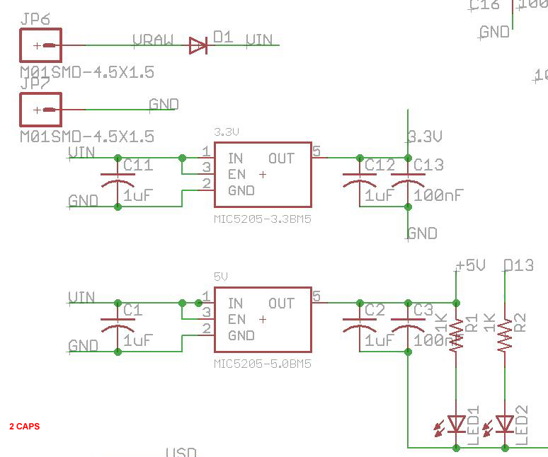
I went back and looked at a schematic I made (and posted for review).. and noone seemed to point that out to me on this project??
How crucial is it to have TWO caps in parallel on the regulated lines from the vReg?
(and Im not thinking that 22uF is WAY to big to have a cap on the input of the vReg lines?)
So for this diagram/schematic..
1.) Is only having the 1 cap (100uF) after the regulator 'ok'? ...single cap? (doesnt match the statement made above though?) (I just ordered the PCB's too!) LOL
2.) Im thinking 22uF is way to big of a value to use? (C1/C2) should I knock it down?
Depends on what the datasheet for the actual regulator says. Most will work with 1uF on input and 10uF on the output, but best to check what the datasheet says, especially for low-drop-out regulators (much more fussy).
xl97:
How crucial is it to have TWO caps in parallel on the regulated lines from the vReg?
Large capacity (eg. electrolytic) capacitors are slow to react. You need to add a small/fast one (eg. ceramic) to take the strain while the big one is starting up.
Actually, bypass and electrolytic capacitors filter noise in different frequency ranges, high and low,
respectively.
Although the capacitive reactance formula, Xc = 1/(2pif*C), indicates that the impedance of a
cap should be even smaller at high-frequencies than at low-frequencies, for real-world electrolytics,
this is not the case [real-world always varies from the ideal]. See curve here,
that is 'faulty'?... and will not work as is? or just be 'slower' (slower for what? to power up?)
but if I need to make changes and re-order...I'd guess I'll have to do that.
Should I just mimic the layout/schematic like in the second image then?...
This forum is totally screwing up lately - I wrote a long post, and it ate it. Short form,
the 2nd image is what you normally see.
you always need both electrolytic and bypass caps on the Vcc buss, although a bypass on the uC
Vcc pins will probably be adequate if not too far from the v.reg.
if the electrolytics are too large, Vcc may come up slowly, and the uC may not boot properly,
but you'll probably not have that problem with values of 1..22 uF.
oric_dan(333):
This forum is totally screwing up lately - I wrote a long post, and it ate it. Short form,
On EVERY forum I post on I copy my message before I post it just in case. I have gotten screwed too many times in too many places not to take the extra third second to hit ctrl-a, ctrl-c
dhenry:
I have had numerous systems running without decoupling caps. It is one of those things that you don't need it until you need it.
So your systems are as good as your answers here, I did wonder.
The thing is that a seemingly functioning system can be just on the edge of functioning and things like ageing of components can push it over the edge. So to use no decoupling capacitor is just asking for it.
It is rare that there is too much decoupling. The only case I have ever encounters is that some DC to DC converters will not start with too much of a capacitave load, and the odd case of low dropout regulators, most are not that fussy.
The ratio of large to small caps is not large. One large cap for every ten or so small ones.
Remember caps are only one aspect of decoupling there is seriese resistors and inductors to consider as well.
An under decoupled system might work but be more prone to disruption by interference. It is only when you start testing the system in the presence of interference can you tell how robust it is going to be.
Getting enough decoupling in the right place accounts for over 85% of all problems in professional development of cutting edge products and warps responsible for more board revisions than anything else.
There are two types of decoupling: bulk decoupling and (device) decoupling. We are talking about the later. For that, you want to have a small but fast capacitor (ceramic or polyethylene). A typical value is 104 monolithic. However, I typically use a 4.7uf electrolytic (for ease).
There are smt electrolytics that are not very large, even for good-sized values like 10...22 uF.
there is no Electrolytic caps even being used (guess that is in incorrect).. I didnt see any +/- in the schematics..where others 'did' have it
People do everything, but as indicated, the best practice is to use both. OTOH, you also need to
check what the datasheet says [as others said]. smt devices may have special directions, such as
cap values within certain ranges.
I have had numerous systems running without decoupling caps.
Ditto to the first sentence of the previous answer.
so to use a ceramic cap is not enough.. or not 'correctly' decoupling the power lines...correct?
it 'must' use a electrolytic cap.. (for the polarity)..
I believe the term 'decoupling' usually refers to the bypass caps [small-valued ceramics]. Also,
tantalum caps are a replacement for electrolytics, and have much better high-frequency
characteristics, but generally cost 20X as much more more.
In the upper right corner of the board is a small yellow block with a brown band on one end... That Sure looks like a tantalum capacitor or at least it looks Exactly the same as the tantalums I used in place of smd electrolytics. for coupling and bypass. Typically I would start with a 220 - 470uF elect. cap on the battery and a 100 uF elect. cap on the output of the regulator MAX683??? I really don't remember but it was an electrolytic and I just wanted 'something' there. I should stop and note that Electrolytics should be about twice as big as calculated because over any appreciable time they will always decrease in value and decrease value with temperature. MLM Ceramic capacitors were relatively new and expensive in 2008 when I retired and I used tantalums whenever I needed a stable and good quality capacitor. I would use at least one 10uF tant or possibly a 47uF tant. Cap on each design along with a 100 nF per IC. From personal experience it pays to be as conservative as possible. There is another thought too... add as many as you have reasonable room for... You don't have to populate the positions of unnecessary parts... and should the part 'somehow' be required... You've a place for it.
Finally the parts are totally invisible, inexpensive, insurance and will not limit the rise time of the regulator output voltage... unless the current limit of the IC is exceeded.