I am not planning to use Vin, so the regulator will not have any power, apart from 3.3V applied to output. I am not familiar with how the output is designed and if the regulator can be damaged or would drain some power.
In the worst case I can just cut the 5th pin connection but if I can avoid altering the board I would prefer that.
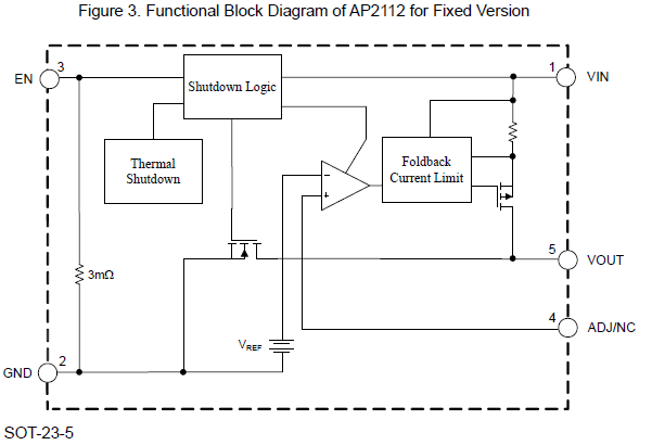
The functional block diagram suggests that you might be able to get away with applying a voltage to Vout, when the regulator is unpowered. But if it will never be powered, just remove it, or cut the PCB trace.
Thanks, yes, I dont think I will ever use it as my project is 3.3V, desoldering it could be challenging, PCB is too fine to cut, but I can easily just clip pin 5, or maybe desolder just this pin and leave it in the air just in case.
What about it? Those are the specs for a 2.5V version of the regulator.
This is what you should be looking at:
What that, and the figure posted in reply #7 means, is that if you apply 3.3V to Vin, somewhere between 3.3V and 3.15V (at 600 mA) will appear at Vout, depending on the current draw.
Low dropout regulators like this are used on these modules, so that you can power them either with 5V or 3.3V (applied to Vin). The rest of the parts will function fine at 3.0V or a bit lower.