I am attempting to make a simple driver for a 1W LED, it is only supposed to flash (short arduino pin high).
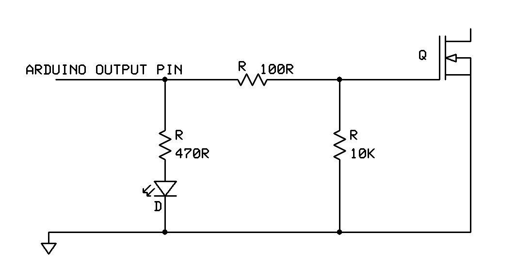
Anyway, i hook up the led and the mosfet as in the schematic:
The trouble is that the led is always shining with half brightness, and when i trigger the arduino pin it shines at full brightness. So the question is, why is it always half-on? I triple checked the DGS pins and they were all in the correct place.
Mosfet datasheet: http://www.seeedstudio.com/wiki/images/e/e7/0440200P1.pdf
As TOM already mentioned the LED in serial with the gate is wrong. You have a voltage drop due the LED and as an effect of this the gate voltage will be to low. Try and you will see that it works (for all logic level N-Channel MOSFET). That's one of the basic schematics.
If you plan to run the power LED with PWM then you may have to reduce the gate resistor.
Ok.. But how does that explain the load being half on all the time. i.e. i cannot turn it off.
Even if i short the LED: same problem. As i said, when i power the pin the load will be at full power, so that works. But if i do not power the pin, it if half on..?
Thanks but you're showing a PNP mosfet. Does someone that has actually read the question and datasheet know what the problem is? I have a firm grasp of the material but it might be something to do with the MOSFET i am using. The question would then be; is the mosfet that i'm showing at all suited for what i attempt/schematic?
That was N-channel NPN MOSFET, I was making a reference to others who want to learn about MOSFETs, how they work, how to connect, if they want how to extend their knowledge about MOSFETs. Page has a link to YouTube video described as
"More Information
If you want to know more, or actually know what is actually going on in there. Pete over at Sparkfun put out amazing video explaining MOSFETs for a solid 20min. Highly recommended."
Your MOSFET suited for this circuit. 12 V 1W Led draws approximately 0.09 A, your MOSFET rated as "Continuous Drain Current 2.1 A" and "Drain-Source Voltage 20 V"
Thanks. If the MOSFET is suited, then why is this behavior? Even if i tie the gate and source together to ground, it stays half on at around 10v (when i supply 12). Then, when i turn on the arduino pin, it gives indeed 12V as it should.
Are you connecting both 12V Power Supply's and Arduino's Grounds together ? Take out led and resistor series to it, just remain the pull-down resistor check Mosfet's behavior again.
first correct your schematic (redurce also the size of the resistor between gate and GND to 100k)
then correct your wiring
then CHECK THAT IT IS WIRED AS IN THE SCHEMATIC
I'm sure that strange behaviour is not because of your MOSFET. I guess it is simply not wired correctly!
TimZaman:
Thanks. If the MOSFET is suited, then why is this behavior? Even if i tie the gate and source together to ground, it stays half on at around 10v (when i supply 12).
The only explanation for that is:
a) An incorrectly connected MOSFET
b) A broken MOSFET.
@mgcss:
I had this assembled. it's not wired. it's a PCB. and, it's pre-assembled. I checked all wires and routes, everything checks out. Except the MOSFET. Therefore i thought i might have chosen the wrong mosfet model. I might have a shitty mosfet batch, they were too cheap i guess.
But i think these MOSFET's are bogus, then i have to agree with fungus. I will verify this by hooking up another MOSFET. Thanks.
MOSFETs have a leakage current, which for a beefy power device will be much higher than
you might think. If you want to guarantee full turn off of the 12V strip add say 4k7 in
parallel with it, this will dump all the leakage current (which should be << 1mA).
LEDs have a light intensity proportional to the current, but the eye is roughly logarithmic
in response - we can see a brightness ratio of thousands, so even a fraction of 1mA
flowing through the LEDs will be visible to the human eye.
Alternatively the MOSFET might be damaged (excessive leakage is common in
damaged semiconductors). Check the datasheet for the expected leakage current
for your particular MOSFET - if it leaks more than that its been damaged (by
over temperature, or static electricity, most likely).
[ Looking at the datasheet the leakage is small, 1uA, so its likely damage. That
device as abs-max Vgs of +/-8V so its not really suitable for driving from 5V supply,
too close to the limit - at the very least add a 5V6 zener directly across gate+source
as protection from supply spikes if you use such a sensitive device ]
Finally response from people with knowledge. The past few commenters were all correct.
So at first i suspected i might have chosen a wrong mosfet/schematic errors. Nope.
(1) The MOSFET's were damaged. I had these PCB's made, some MOSFETs worked, some didnt. What i did was desolder one that worked, one that was damaged. Then i swapped them around and desoldered them. The one that failed before, failed again even in the place where the other worked. The one that worked, worked also in its new place. Hence, the MOSFET's were broken.
I suspect shitty assembly or a batch of shitty parts. I'll have them remade.