Hello, I'm attempting to replicate this research paper to build a potentiostat for one of my research projects.
All of the parts I have are listed in the paper and compatible with a solderless breadboard. For the OpAmps, I have LM324AN.
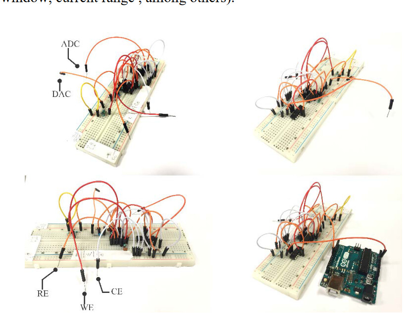
I only have a basic understanding of how to construct a circuit, so I need just need a visual representation of how I should start this circuit or any tips would be super helpful!
You plug the IC into the middle of the breadboard and start inserting wires to make the connections that you see in the schematic you have. Hmmm. There are actual sample images of that in the document that you linked do. Is there something you didn't like about the way they did it?
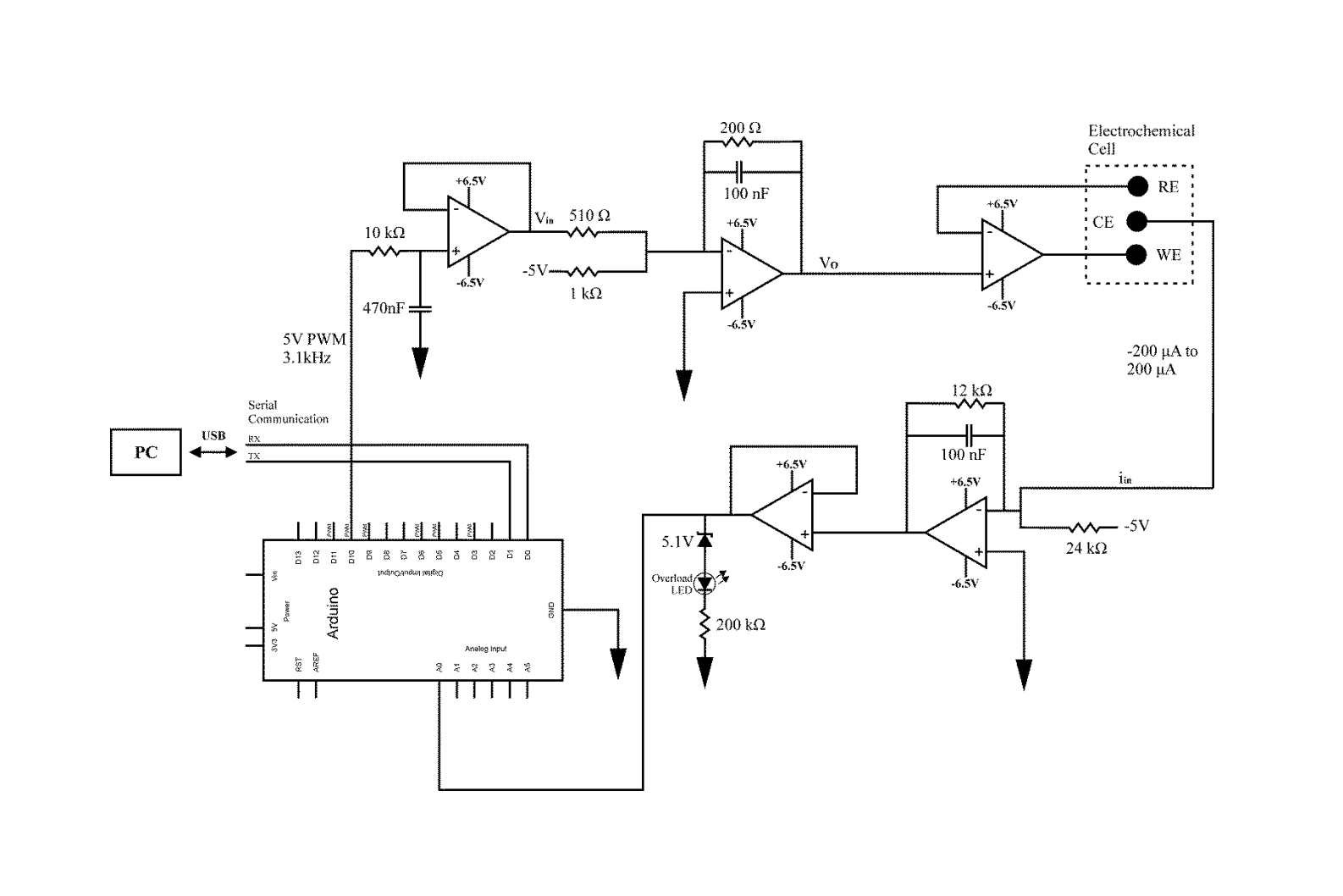
The schematic in the paper doesn't list the pin numbers on the two LM324 quad Op-Amp ICs. That could be a bit daunting. I'd choose one IC for the top three op amps in the schematic, and the other for the bottom two.
In that case you REALLY NEED to build some simple circuits first.
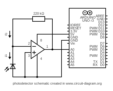
Remember the organisation of components on the schematic is NO INDICATION of the physical layout. Here is something you could try - at a pinch you can use an LED instead of a photodiode
As your op amps are 4 in a package you will need to use different pin numbers - so eg
Vcc+ (5V) pin 4: Vcc- (gnd) pin 11. all others same.
And I suggest reading this that may give you a better understanding of how shematics represent circuits
You should be aware that the circuit as designed requires a dual power supply - one that can supply both VDC+ and VDC-. The authors simply suggest using an old ATX PC power supply but there are no instructions or schematic, so you will have to address either buying one or building one.
Also you have summing and trans-impedance op-amp configurations in the circuit which are more challenging to understand than a simple non-inverting amplifier.
My personal observation is that people attempting to build circuits with op-amps and no understanding of their characteristics are generally not very successful. I strongly suggest you work through a program of tutorials on op-amps, building and studying test circuits of each of the common op-amp configurations starting with unity gain buffer, non-inverting, inverting, differential, instrument, summer, trans-impedance.
To add to what you said, I would avoid using a breadboard for something like this. Either use a protoboard, or assemble the parts on a section of copper-clad PCB dead bug style
You don't need an opamp buffer that buffers a buffer for the overload LED.
The LED opamp can output a negative voltage, which will destroy the A0 pin.
The LED has a 200k CL resistor, which is too high. They probably meant 200 ohm.
I would remove the LED opamp, and use a 10k resistor between the bottom/right opamp output and A0. Add a Schottky diode between A0 and ground for negative voltage protection of the pin. Then connect the LED/resistor (no zener) to a different Arduino pin, and control the function of the LED in software.
Leo..